Dustless spout assembly

a spout and assembly technology, applied in the direction of chutes, loading/unloading, transportation and packaging, etc., can solve the problems of dust, fines and dust, damage to grain and other particulate materials, etc., to reduce the dust escaping the flowing material and the effect of reducing the flow

Inactive Publication Date: 2016-12-22
RUZICKA BO JAMES P
View PDF3 Cites 8 Cited by
  • Summary
  • Abstract
  • Description
  • Claims
  • Application Information

AI Technical Summary

Benefits of technology

The invention is a device that helps control the flow of particulate materials (like grain) in a conduit. It uses plates that are controlled by a counterbalance mechanism to adjust the force on the plates and reduce damage to the material. A divider is used to create a void region to control dust, and a funnel is used to help direct the material flow. Overall, this device helps regulate the flow of particulate materials and minimize the escape of dust during the transfer process.

Problems solved by technology

Grain and other particulate material falling uncontrolled at high velocities causes: (1) damage to the grain and other particulate material and (2) creates dust.
The damage is apparently caused by particle-to-conduit abrasion and particle-to-particle impact, and these interactions cause fines and dust.
A free-falling stream of such material tends to reach a terminal velocity because the air currents within and around the stream cause turbulence when the stream is unconfined.
Damage to the material and creation of dust as the result of high conduit velocities also occurs with materials other than grain, although it is most important in respect to grain because of the relative frangibility and layered structure of grain kernels.
However, it is difficult to avoid a substantial elevation change in many instances, as for example in loading grain or other particulate material into the hold of a ship.
A flow restriction in the path of the falling material may slow the material velocity.
However, dead boxes are effective primarily in those situations where the grain or other particulate material flow rate (i.e., bushels per hour) is constant or within a relatively narrow range so as to avoid “surges.” However, constant velocity is not usually the case.
Non-uniform moisture content in the grain or other particulate material is another cause of surges.
When the flow rate is uneven, the use of a fixed restriction such as a dead box to retard flow is of little effect.
This can cause bridging or clogging which can choke off flow completely.
In addition to the problem of damage to the grain or particulate material due to high falling velocities, air entrained within the falling stream is a significant problem due to the creation of dust.
Furthermore, the work environment is clouded by the dust and workers have difficulty seeing for secure footing and evaluation of the level of fill of the vessel receiving the grain or particulate material.
However, the adjustability of the biasing mechanism disclosed in these patents in some instances is inadequate.
As the conveyor moves, the grain is turning over and over and the mineral oil coats the grain, resulting in the dust attaching to the grain.
However, a large quantity of mineral oil must be applied to sufficiently limit the dust, and often the mineral oil absorbs into the grain, dimensioning the mineral oil's effectiveness in controlling dust.

Method used


Image

  • Dustless spout assembly
  • Dustless spout assembly
  • Dustless spout assembly

Examples


Embodiment Construction

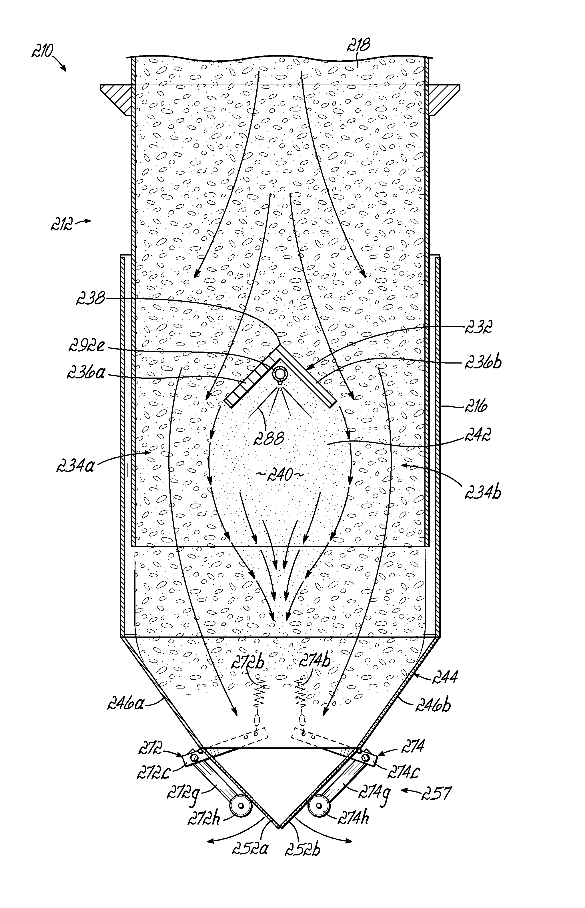
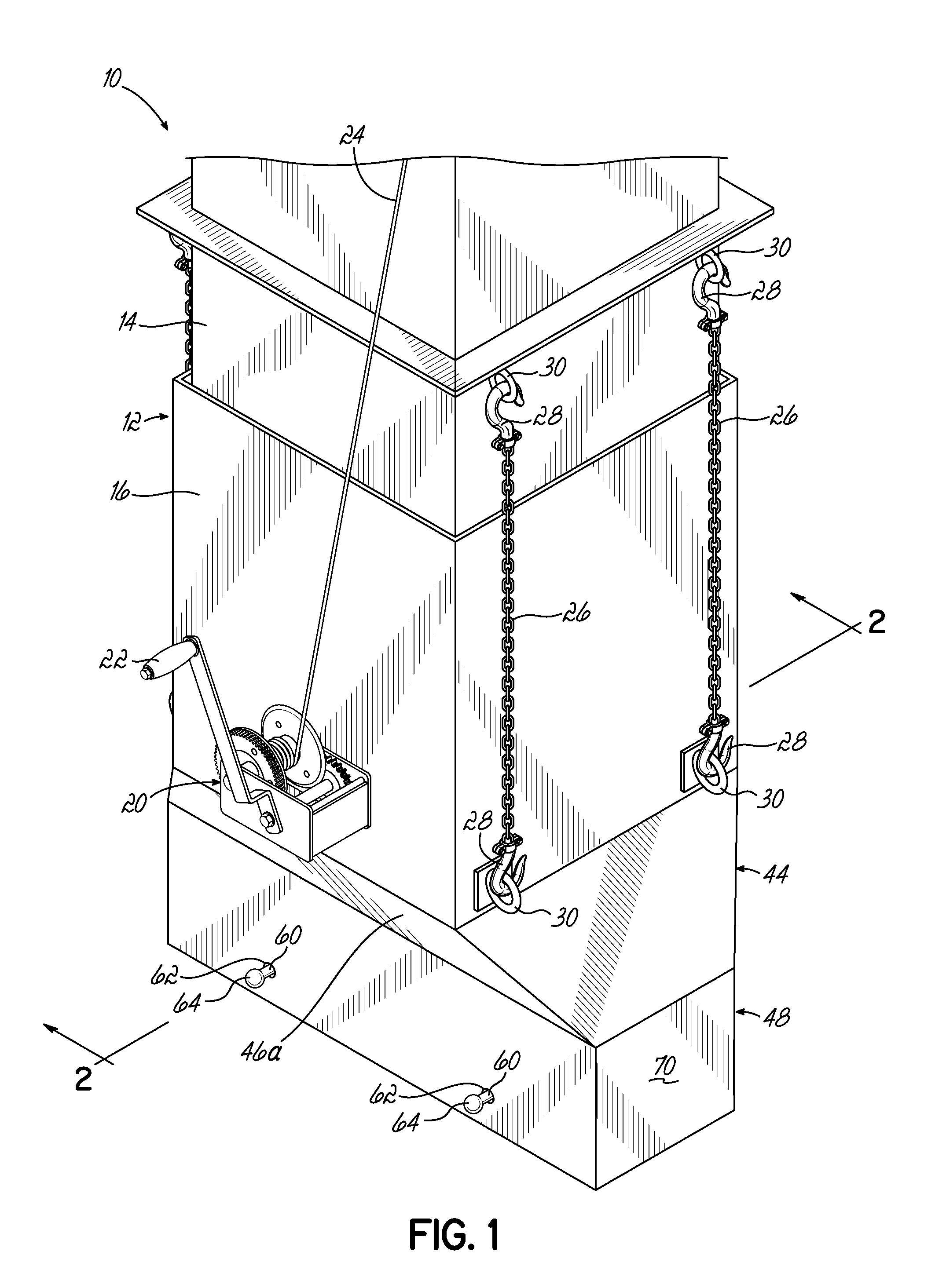
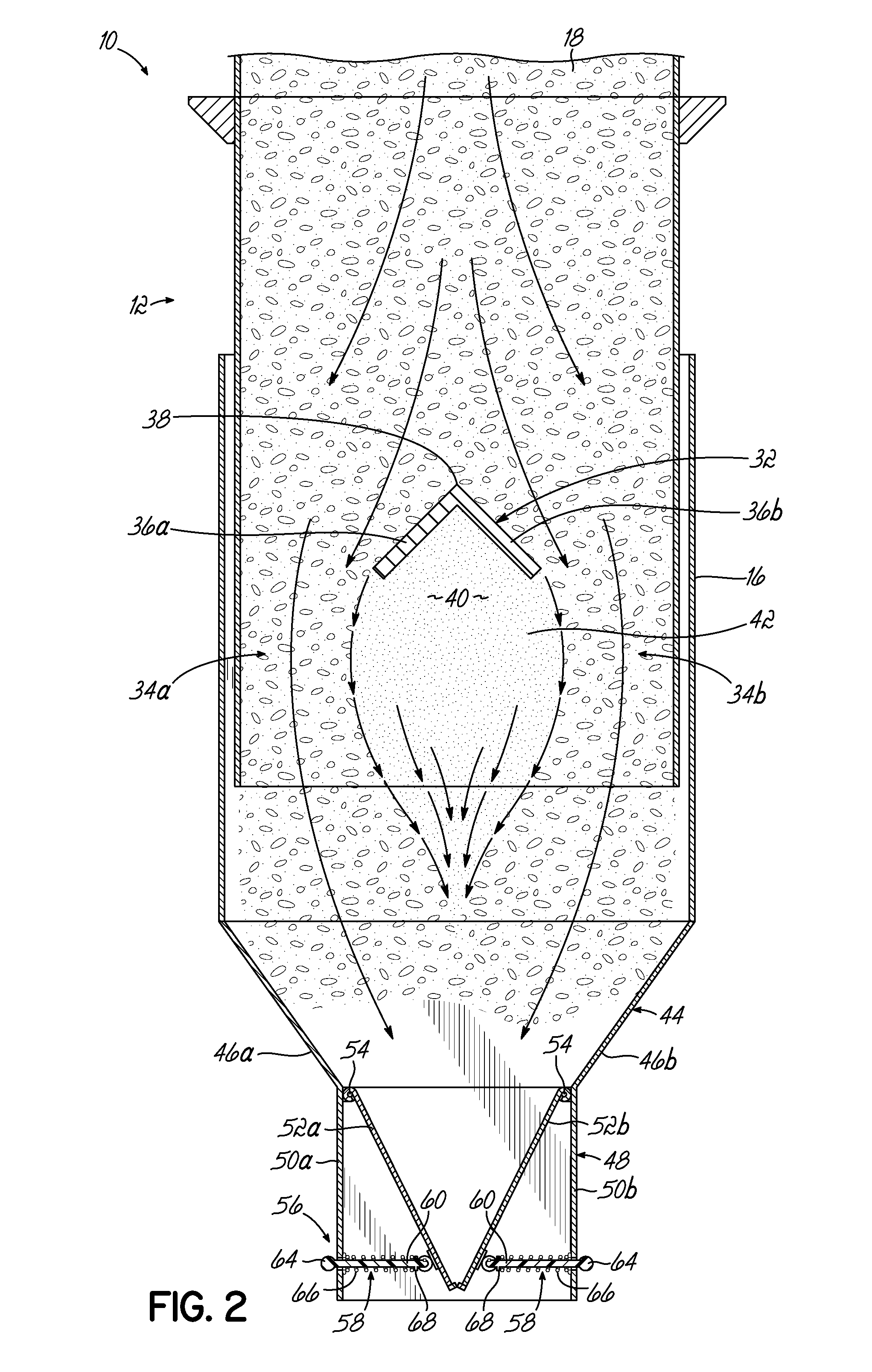
[0033]Referring to FIG. 1, a perspective view of one embodiment of a dustless spout assembly 10 according to this invention is shown. Cross-sectional views of the spout assembly 10 are likewise shown in FIGS. 2-3B. The assembly 10 includes an upper chute section 12 formed by an upper and a lower chute 14, 16 telescopically mated together. While two chutes are shown and described, this invention is not limited to two chutes and only one chute or more than two chutes can be used. The upper chute 14 is received within the lower chute 16 as shown in FIG. 2. In one embodiment, the outer perimeter dimension of the lower chute 16 is 23 inches by 23 inches and the similar dimensions of the upper chute 14 are likewise designed to matingly fit within the lower chute 16. In operation, the spout assembly 10 is adapted for the transfer of grain, corn or other particulate material 18 in a generally vertical downward direction from a supply of grain 18 into a rail car, cargo hold or other receptac...


PUM


Abstract

A spout assembly and related method of regulating the flow of particulate material. The spout assembly includes a chute, at least first and second plates, and a counterbalance mechanism. The first and second plates are positioned downstream from the chute, the lower ends of the first and second plates defining an opening with an area that is smaller than a cross-sectional area of the chute so that the material may accumulate prior to passing through the opening. The counterbalance mechanism produces a biasing force on the first and second plates toward the centerline to adjust the area of the opening, and permits the first and second plates to move outwardly away from the centerline in response to the weight of the accumulated material. The counterbalance mechanism includes at least a first separately adjustable counterbalance coupled to the first plate and a second separately adjustable counterbalance coupled to a second plate.

Description

[0001]This application is a continuation-in-part of application Ser. No. 14 / 248,381, filed Apr. 9, 2014 which claims the priority of U.S. Provisional Patent Application Ser. No. 61 / 811,339, filed Apr. 12, 2013, the disclosures of which are hereby incorporated by reference herein.BACKGROUND OF THE INVENTION[0002]Grain and other particulate material falling uncontrolled at high velocities causes: (1) damage to the grain and other particulate material and (2) creates dust. The damage occurs both during fall in a downwardly inclined conduit, as well as upon impact after discharge from the conduit. The damage is apparently caused by particle-to-conduit abrasion and particle-to-particle impact, and these interactions cause fines and dust.[0003]The velocity increase of the material is most rapid in a vertical conduit, but even in a slanting conduit, velocities of several hundred feet per minute are attained in a few feet. A free-falling stream of such material tends to reach a terminal vel...

Claims


Application Information

Patent Timeline
IPC IPC(8): B65G69/18B65G11/16B65G11/14
CPCB65G69/188B65G2201/042B65G11/166B65G11/146B65G11/206
Inventor HARAWAY, COY N.RUZICKA, BO JAMES
Owner RUZICKA BO JAMES P
Why Eureka
Try Eureka