Optical scanner device
a scanning device and optical scanner technology, applied in the direction of instruments, optical elements, discharge tubes/lamp details, etc., can solve the problem of distorted image generated based on reflection which is not accurately controlled, and achieve the effect of higher accuracy
- Summary
- Abstract
- Description
- Claims
- Application Information
AI Technical Summary
Benefits of technology
Problems solved by technology
Method used
Image
Examples
first embodiment
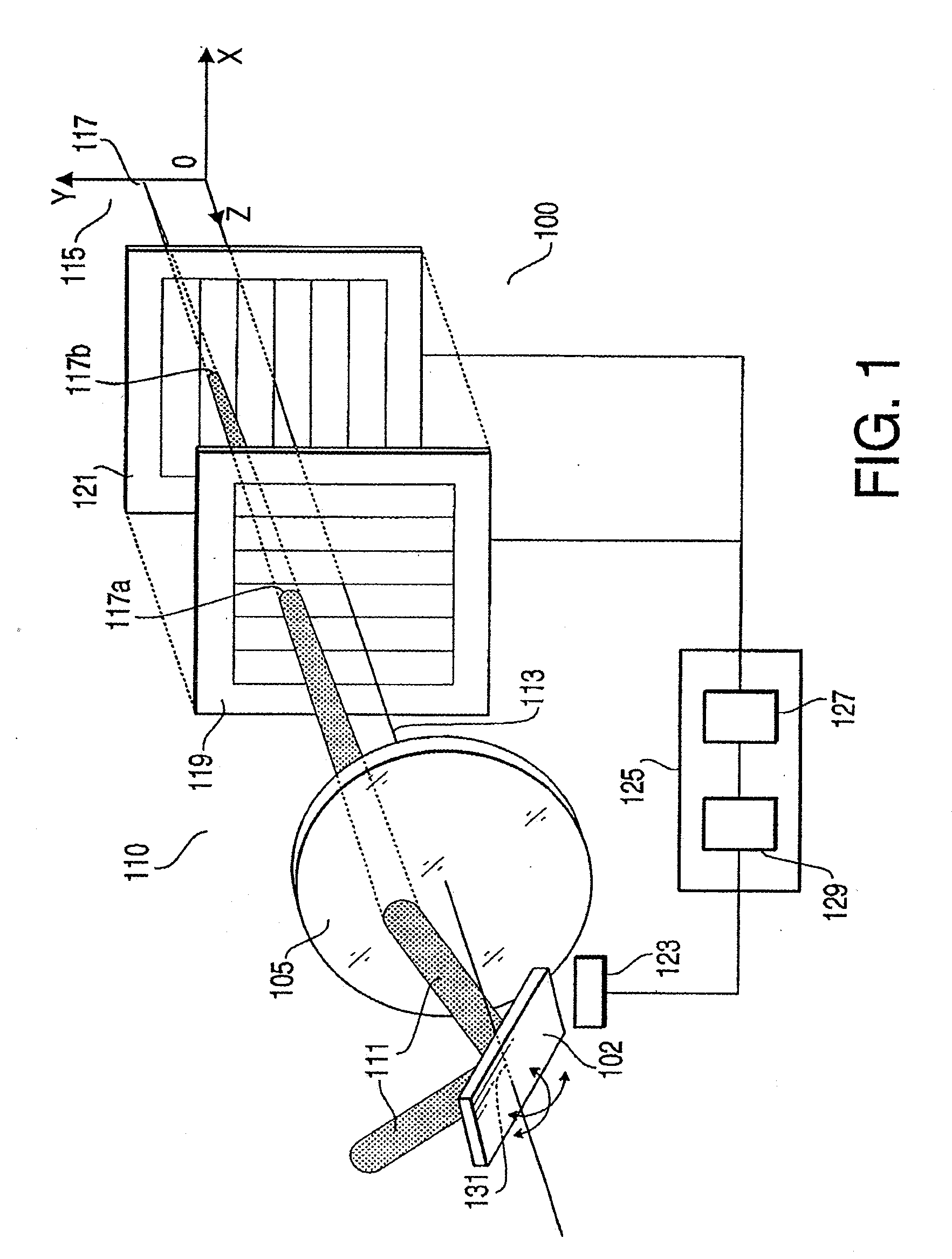
[0045]FIG. 1 shows an optical scanner device 100 with photo-detector elements arranged on an optical axis thereof according to a first embodiment of the present invention. The optical scanner device 100 includes an optical system 50 and a control system 60 (see FIG. 2). The optical system 50 includes a light source 150, a mirror unit 102, a light spot position detector unit 110. The control system 60 includes a control unit 125. The light spot position detector unit 110 is provided with an objective lens system 105, a photo-detector element 119, and a photo-detector element 121. It should be noted that an optical axis of the objective lens system 105 is also referred to as an optical axis 113 of the optical scanner device 100.
[0046]The mirror unit 102, the objective lens system 105, the photo-detector element 119, and the photo-detector element 121 are respectively arranged on the optical axis 113. In the optical scanner device 100, irradiation light 111 such as laser beam supplied ...
second embodiment
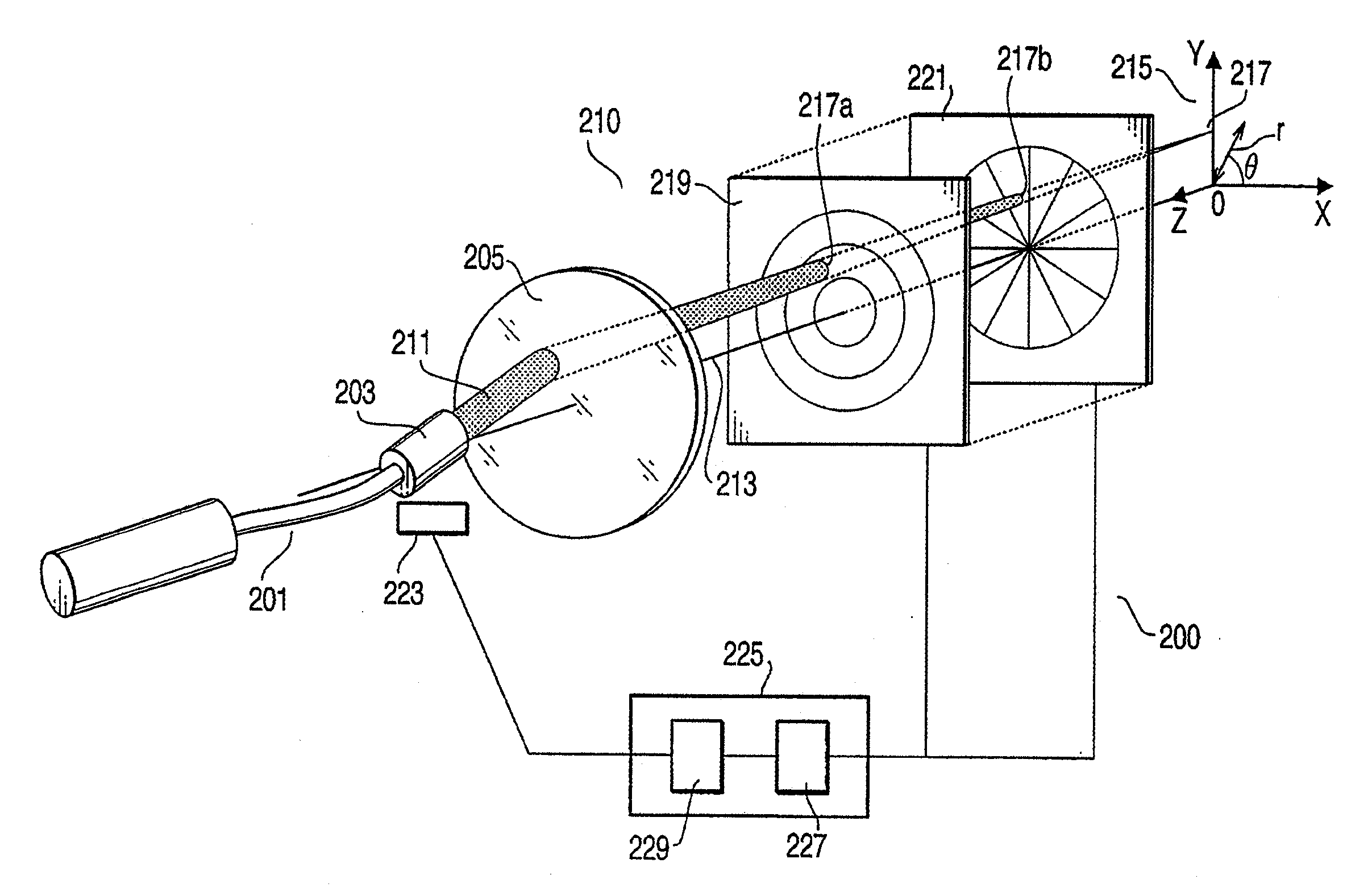
[0062]Next, an optical scanner device 200 to obtain a position of a light spot based on a polar coordinate system (r, θ) according to a second embodiment of the present invention will be described.
[0063]FIG. 5 shows an optical scanner device 200 with photo-detector elements arranged on an optical axis thereof according to a second embodiment of the present invention. In the present embodiment, description of a configuration being similar to the configuration described in the first embodiment will be omitted. The optical scanner device 200 includes an optical system 51 (see FIG. 2) having an optical fiber unit 201, a light spot position detector unit 210, and a control system 61 (see FIG. 2) having a control unit 225. The light spot position detector unit 210 includes an objective lens system 205, a photo-detector element 219, and a photo-detector element 221. It should be noted that an optical axis of the objective lens system 205 is referred to as an optical axis 213 of the optical...
PUM
| Property | Measurement | Unit |
|---|---|---|
| diameter | aaaaa | aaaaa |
| diameter | aaaaa | aaaaa |
| Diameters | aaaaa | aaaaa |
Abstract
Description
Claims
Application Information
 - R&D
- Intellectual Property
- Life Sciences
- Materials
- Tech Scout
- Unparalleled Data Quality
- Higher Quality Content
- 60% Fewer Hallucinations
Browse by: Latest US Patents, China's latest patents, Technical Efficacy Thesaurus, Application Domain, Technology Topic, Popular Technical Reports.
© 2025 PatSnap. All rights reserved.Legal|Privacy policy|Modern Slavery Act Transparency Statement|Sitemap|About US| Contact US: help@patsnap.com


