
Non-invasive disease diagnosis using light scattering probe

a light scattering probe and non-invasive technology, applied in the field of non-invasive disease diagnosis, can solve the problems of limited success of conventional raman spectroscopy, weak raman scattering signal for trace chemical detection, and limited application of conventional raman sensors

Active Publication Date: 2009-04-02
EXCELLENT CAPACITY LTD
View PDF14 Cites 27 Cited by
  • Summary
  • Abstract
  • Description
  • Claims
  • Application Information

AI Technical Summary

Benefits of technology

[0014]Embodiments may include one or more of the following advantages. The disclosed systems and methods provide simple and non-invasive approach to detect a disease in a patient. The disclosed systems are portable and easy to operate, and are thus ideal for being used for early disease prevention, and in-field drug usage screening. The disclosed systems and methods are suitable for early detect and diagnosis. The disclosed systems and methods also have short testing cycle, and can therefore be very helpful for monitoring progresses in the treatment of diseases and drug use. The disclosed systems and methods can detect a wide range of disease such as oral cancer, breast cancer, lung cancer, stomach cancer, liver cirrhosis, a failing kidney, ulcer cancer, ovarian cancer, uterus cancer, cervix cancer, oral cancer, esophageal cancer, thyroid cancer, larynx cancer, leukemia, colon cancer, bladder cancer, prostate cancer, bronchus cancer, diabetes, HIV, smoking status as well as illicit drug use.
[0016]Furthermore, a wide range of applications that should be achievable with relative low Raman sensitivity detections implementing conventional Raman Scattering were also overlooked and neglected due to low expectation of Raman sensing capabilities. New and improved Raman sensing applications are also disclosed in this invention that do not require high detection sensitivities and do not require surface enhanced Raman sensing devices such as such sensor applications. The embodiments disclosed in this invention thus expand the fields of applications for devices that implement Raman scattering sensing technologies.

Problems solved by technology

Despite the fact Raman detectors have sensitivity down to a level of single molecule detection (SMD), due to several technical difficulties; conventional Raman sensors still have very limited applications.
Specifically, one of the major limitations of Raman spectroscopy application is the weak Raman scattering signal for trace chemical detection.
However, such efforts still have very limited success and have not been able to make Raman detectors available for practical and economical applications that urgently require ultra sensitive chemical trace detections.
However, the conventional technologies, for example, VLSI lithography technology, are still encountered with technical difficulties to fabricate nano-structure surfaces with reduced dimensions of the nano-particles and reduced distance among these nano-particles on the surface to achieve scattering signal enhancement.
The very limited availability of non-contaminated nano-structured noble metal surface is still a major difficulty faced by those of ordinary skill of the art in applying the technologies of SERS (Surface-Enhanced Raman Scattering) and SERRS (Surface-Enhanced Resonant Raman Scattering) for trace chemical detection.
Due to this limit availability, even though the detection of trace chemicals can be achieved a part-per-billion (ppb) level, the techniques of applying SERS and SERRS for detecting trace of explosives and / or other chemical materials still have very limited applications.
However, these publications do not provide an effective method to produce and package the non-contaminated nano-structured noble metal surface to achieve field applications of SERS and SERRS for trace chemical detection.
Furthermore, none of these publications provide method to fabricate nano-structured materials with well-controlled nano array that have reduced and optimized dimensions of the nano-particles and reduced and optimized distances among these nano-particles on the surface to achieve scattering signal enhancement.

Method used


Image

  • Non-invasive disease diagnosis using light scattering probe
  • Non-invasive disease diagnosis using light scattering probe
  • Non-invasive disease diagnosis using light scattering probe

Examples


Embodiment Construction

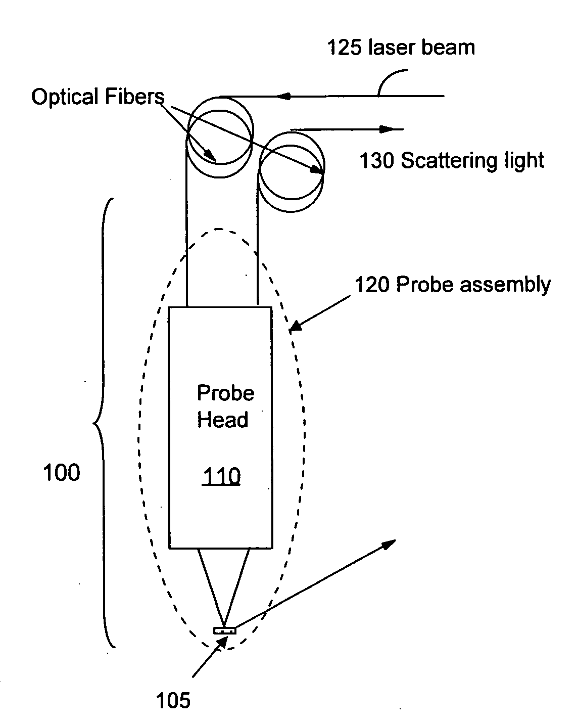
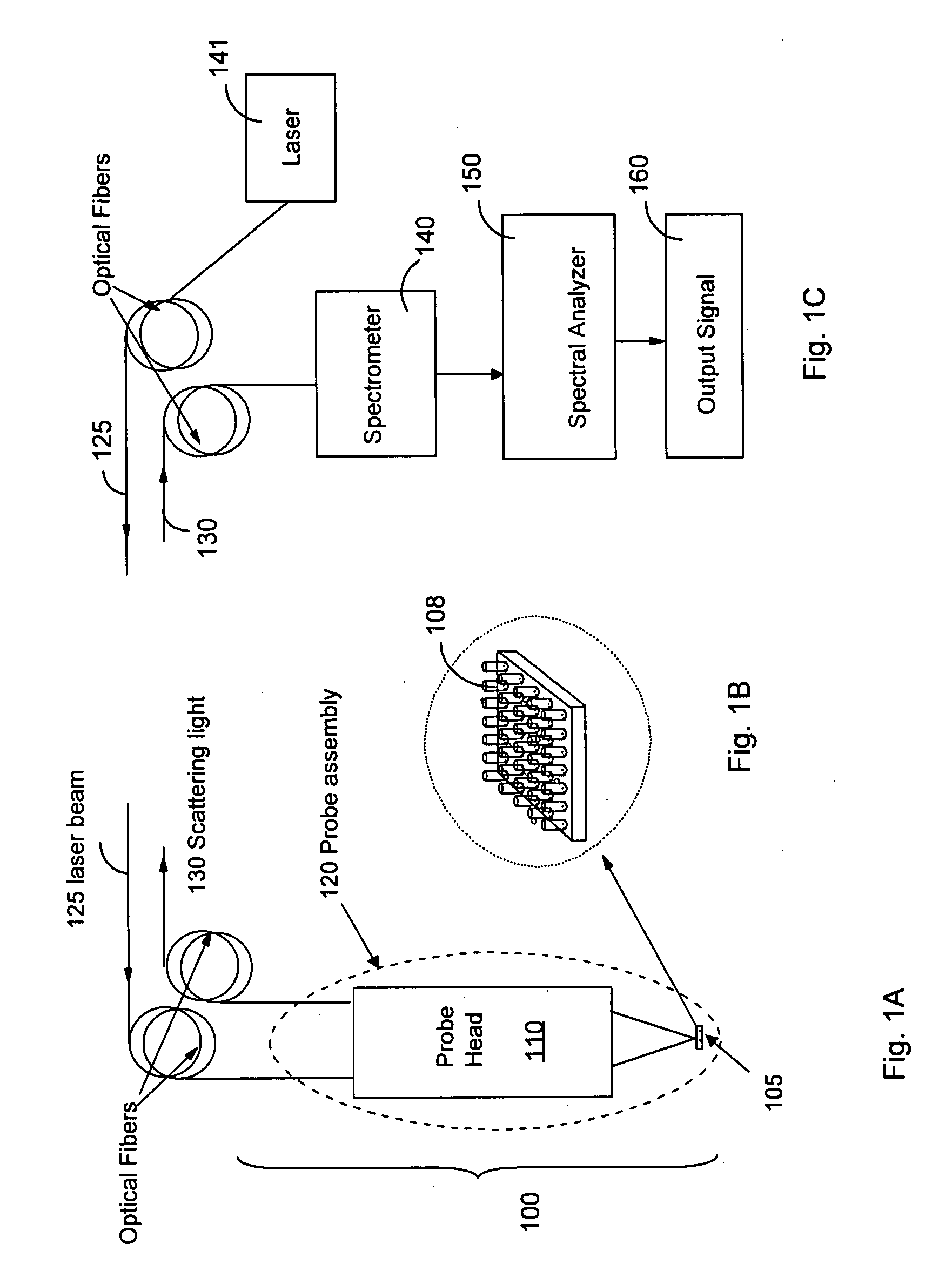
[0047]Referring to FIG. 1A, a light scattering probe 100 includes a probe head 110 and a sensor 105 (such as a RamanNanoChip™). As shown in FIG. 1B, a sensor 105 includes a plurality of nano rods 108 (or holes). A body fluid is obtained from a patient or an illicit drug user and applied to the sensing surfaces of the sensor 105. Examples of the body fluid can include blood, saliva, urine, serum, tear, sweat, and stomach fluid. The probe head 110 and the Sensor 105 are enclosed in a probe assembly 120. The probe assembly 120 can be depressurized by a vacuum pump to reduce contamination of the sensing surfaces for foreign substance.

[0048]A laser beam emitted by a laser 141 is guided by optical fibers 125 to illuminate the sensor 105, as shown in FIG. 1C. The probe head 110 is positioned adjacent to the sensor 105. In the present application, the term RamanNanoChip™ refers to a sensor comprising a nano-scale surface structure that is configured to adsorb molecules of a chemical, biolog...


PUM


Abstract

A method for non-invasive detection of a disease, a status of illicit-drug use, or smoking status includes transferring a body fluid obtained from a patient to a sensor comprising a nano-scale surface structure to allow the body fluid to come in contact with the nano-scale surface structure, illuminating the body fluid and the nano-scale surface structure by a laser beam, scattering the laser beam by the body fluid and the nano-scale surface structure to produce a scattered light, and analyzing the scattered light using a spectral analyzer to diagnose a disease, the status of illicit-drug use, or smoking status in the patient.

Description

[0001]The present application is a Continuation-in-Part (CIP) patent application of commonly assigned pending U.S. patent application Ser. No. 11 / 681,157, entitled “Trace chemical optical probe”, filed Mar. 1, 2007. U.S. patent application Ser. No. 11 / 681,157 is a continuation application of commonly assigned U.S. patent application Ser. No. 10 / 987,842 (now issued as U.S. Pat. No. 7,242,469), which is a CIP patent application of U.S. patent application Ser. No. 10 / 852,787 (now issued as U.S. Pat. No. 7,384,792) filed on Mar. 24, 2004. U.S. patent application Ser. No. 10 / 852,787 claims priority to Provisional Patent Applications 60 / 473,283 and 60 / 473,287 filed on May 27, 2003, and Provisional Patent Application 60 / 520,222 filed on Nov. 17, 2003.BACKGROUND[0002]This invention relates generally to the methods and systems for detection of very small amount of chemicals (trace chemicals) by employing light scattering probes. More particularly, this invention relates to an improved light ...

Claims


Application Information

Patent Timeline
Patent Type & Authority Applications(United States)
IPC IPC(8): G01J3/44
CPCG01J3/02G01J3/021G08B21/12G01N21/658G01J3/44
Inventor WANG, HONGGUO, XUN
Owner EXCELLENT CAPACITY LTD
Learn More