
Beam dump for a very-high-intensity laser beam

a laser beam, very high-intensity technology, applied in the direction of optical elements, manufacturing tools, instruments, etc., can solve the problems of affecting the design of the beam-terminator, the tip of the cone can melt due to a large heat concentration, and the structure arrangement is also susceptible to damag

Inactive Publication Date: 2009-03-26
COHERENT INC
View PDF8 Cites 26 Cited by
  • Summary
  • Abstract
  • Description
  • Claims
  • Application Information

AI Technical Summary

Benefits of technology

[0005]The present invention is directed to a terminator for a high-power laser beam. In one aspect, a beam-terminator in accordance with the present invention comprises a thermally conductive body having beam-trapping chamber therein. A curved channel extends into the conductive body. One end of the channel is arranged to receive the laser beam and the other end is in optical communication with the trapping-chamber.

Problems solved by technology

This makes the design of a beam-terminator very challenging.
When such a structure is used with a very high intensity beam, however, the tip of the cone can melt due to a large heat concentration.
This structure arrangement is also susceptible to damage by a high-intensity beam as there is necessarily some beam absorption at each reflection and the first reflection is at near-normal incidence.
While this arrangement is apparently relatively compact and effective in beam termination, the window could quickly become contaminated in an industrial environment.
The contamination would absorb the laser beam which could lead to a run-away absorption condition with a risk of the window breaking and leaking cooling fluid.
It is believed that none of the prior art beam-terminating arrangements is practical for industrial or commercial use with very-high power beams.

Method used


Image

  • Beam dump for a very-high-intensity laser beam
  • Beam dump for a very-high-intensity laser beam
  • Beam dump for a very-high-intensity laser beam

Examples


Embodiment Construction

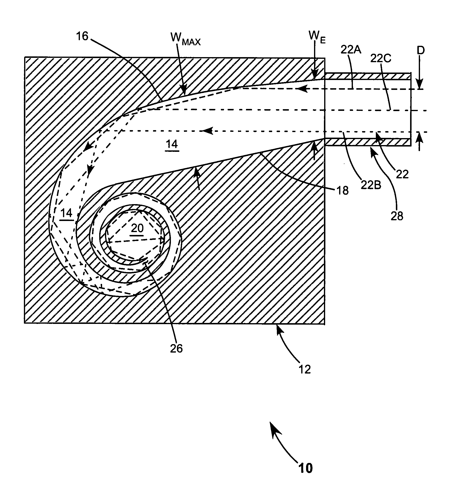
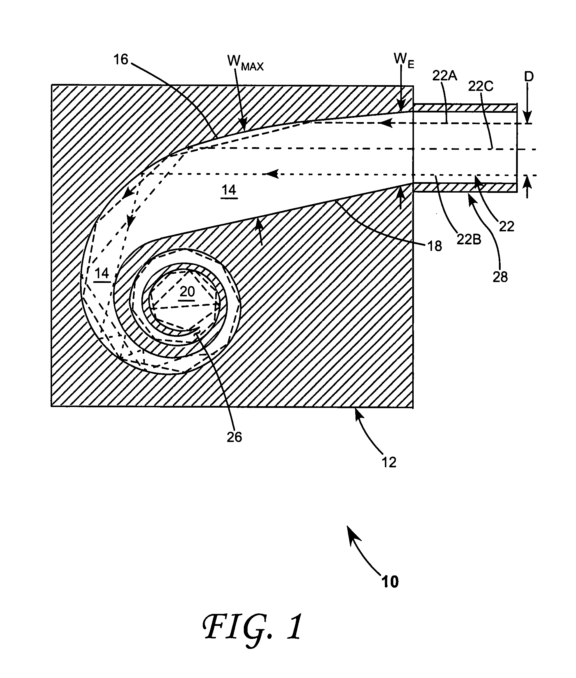
[0012]Referring now to the drawings, wherein like components are designated by like reference numerals, FIG. 1 schematically illustrates one preferred embodiment 10 of a beam-terminator in accordance with the present invention. Terminator 10 includes a body 12 of a thermally conductive material. Suitable materials include but are not limited to copper, copper alloys, aluminum, and aluminum alloys. It is even possible to construct the body from a thermally conductive ceramic such as beryllium oxide or boron nitride.

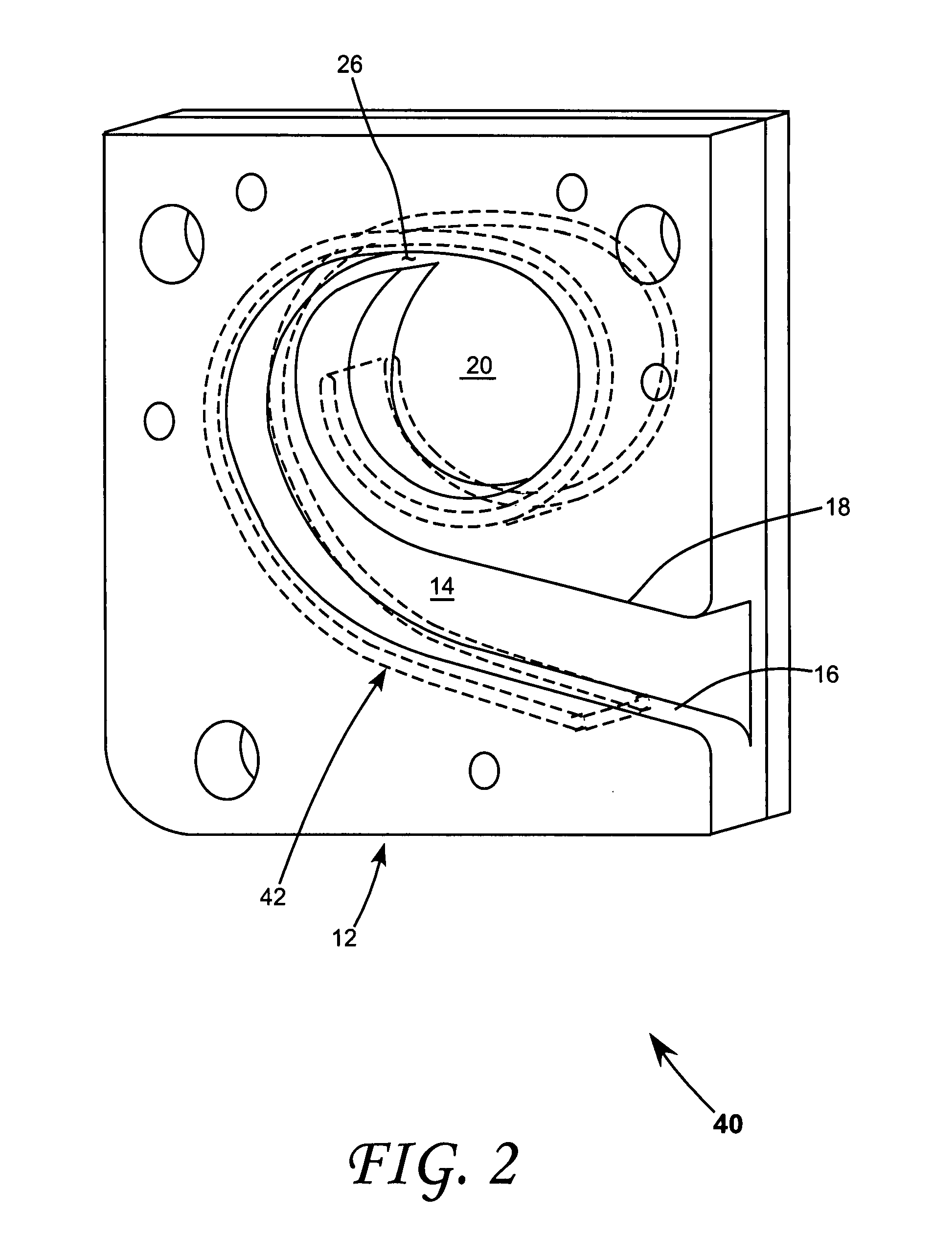
[0013]Included in body 12 is a beam trapping chamber 20. A curved channel 14 leads the beam to the beam trap. Channel 14 has opposite wall 16 and 18 that are used to guide the beam, through multiple reflections therefrom, toward chamber 20. Channel 14 has an entrance width WE larger than the diameter (or maximum dimension) D of a beam 22 being terminated such that radiation in the beam is entirely captured.

[0014]Beam channel 14 is configured to allow the beam to propagate ...


PUM

PropertyMeasurementUnit
angle of incidenceaaaaaaaaaa
thicknessaaaaaaaaaa
thicknessaaaaaaaaaa

Abstract

A beam terminator for a high-power laser beam comprises a thermally conductive body including a beam-trapping chamber. A tapered spiral channel extends into the conductive body for guiding the beam. The beam is partially absorbed while propagating along the channel to the trapping chamber. What remains of the beam is absorbed in the trapping chamber.

Description

TECHNICAL FIELD OF THE INVENTION[0001]The present invention relates in general to terminators or beam dumps for laser beams. The invention relates particular to a beam dump for a laser beam having a very high intensity, for example, 300 W or greater.DISCUSSION OF BACKGROUND ART[0002]High-power solid-state lasers that deliver very high intensity beams for laser machining operations, after being turned on can take up to 5 minutes to reach a stable operating condition. Accordingly during any relatively brief period between operations it is preferable not to turn the laser off. During this period the beam must be terminated, safely, at something other than a work-piece. The beam is terminated at what is usually termed a beam-dump, a beam-terminator or a beam-trap by practitioners of the art. A high-intensity, repetitively pulsed laser beam can reach an average power level from a few hundred (W) to several kilowatts (kW). This makes the design of a beam-terminator very challenging.[0003]...

Claims


Application Information

Patent Timeline
Patent Type & Authority Applications(United States)
IPC IPC(8): G02B27/00
CPCG02B5/003G02B17/004G02B19/0047G02B19/0023H01S3/005
Inventor PANG, H. YANGHARRYMAN, DONALD E.BRAND, WILLIAM CLAYTON
Owner COHERENT INC
Learn More