
Beam line for a source of extreme ultraviolet (EUV) radiation

a beam line and radiation source technology, applied in the direction of optical radiation measurement, instruments, condensers, etc., can solve problems such as lens breakag

Inactive Publication Date: 2013-05-30
ETH ZZURICH
View PDF23 Cites 8 Cited by
  • Summary
  • Abstract
  • Description
  • Claims
  • Application Information

AI Technical Summary

Benefits of technology

This patent aims to create a safe and controllable way to manage the light beams from an extreme ultraviolet (EUV) radiation source. The invention also ensures that debris is prevented from entering the beam entrance port of the enclosure. The technical effects of this invention are improved safety and control of the beam line, as well as prevention of debris contamination.

Problems solved by technology

The problems addressed by the patent and caused by the plasma and debris generation are the following: The focusing lens gets hot and covered by contaminants; this can cause the breaking of the lens.

Method used


Image

  • Beam line for a source of extreme ultraviolet (EUV) radiation
  • Beam line for a source of extreme ultraviolet (EUV) radiation
  • Beam line for a source of extreme ultraviolet (EUV) radiation

Examples


Embodiment Construction

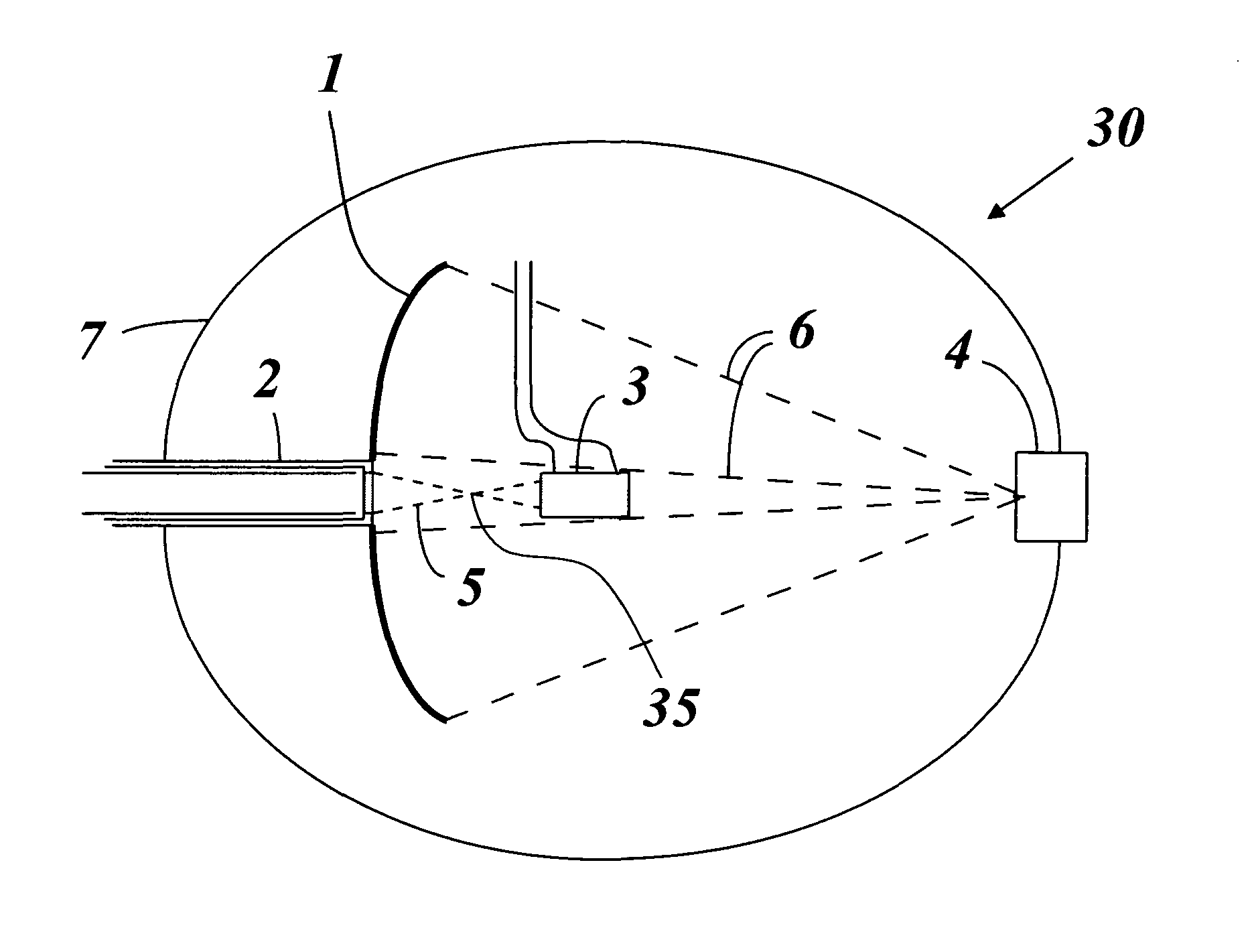
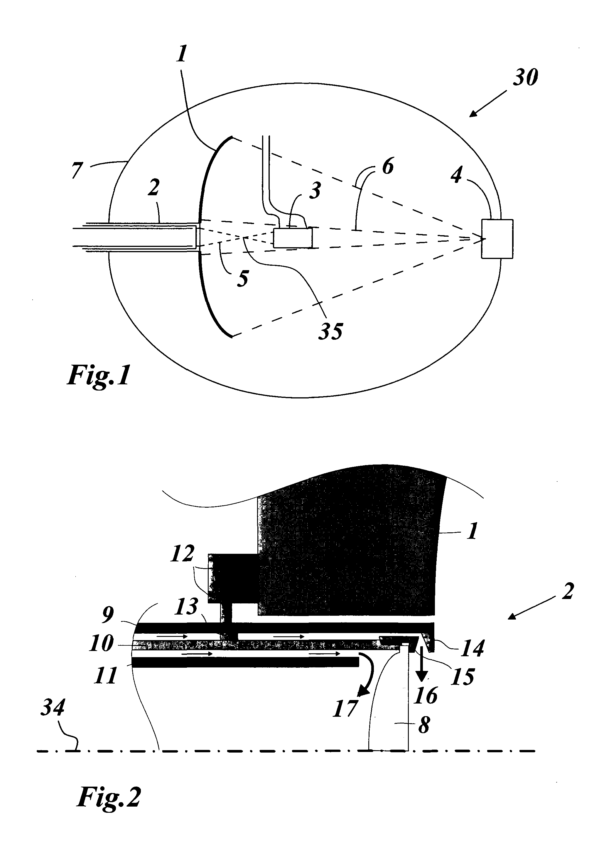
[0049]The beam line 30 according to FIG. 1 comprises at least four elements arranged in a vacuum chamber 7: a laser beam delivery system 2, a laser beam dump 3, a EUV collector mirror 1 with an ellipsoidal shape in operation, and an intermediate focus module 4. Not shown in FIG. 1 is a device for generating droplets of a liquid, e.g. molten Sn, which are ejected to a reach plasma generation point 35, where they are turned into plasma by means of a focused laser beam 5.

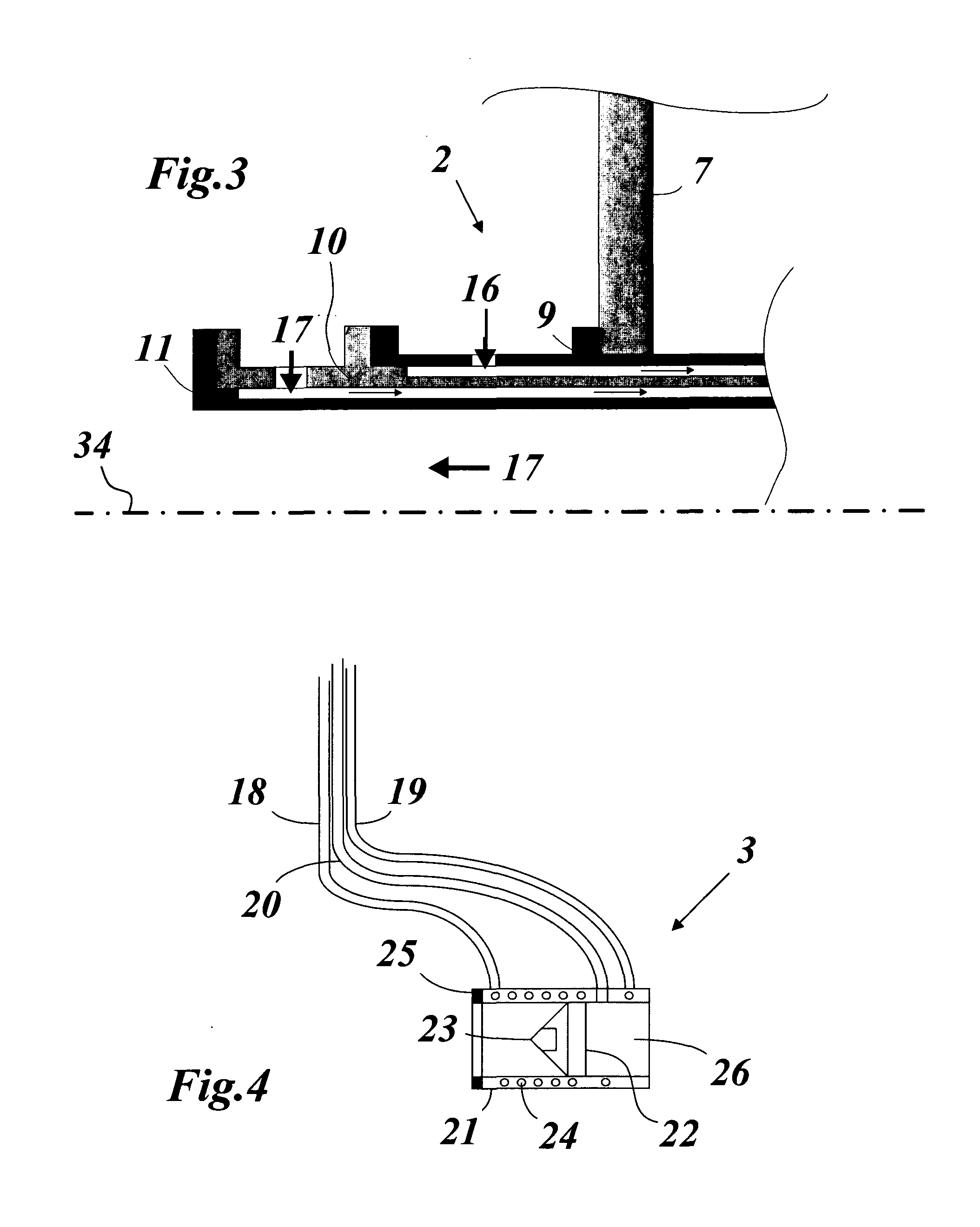
[0050]The beam delivery system 2 shown in FIGS. 2 and 3 is designed to place a focusing lens 8 close to the plasma generation point 35, in order to minimize the spot size dimension (minimize the diffraction) at an intermediate focus located at the intermediate focus module 4.

[0051]The beam delivery system 2 comprises a plurality of concentric tubes, i.e. an outer tube 9, an intermediate tube 10, and an inner tube 11, which reach from the wall of the vacuum chamber 7 to the location of the laser focusing lens 8. The foc...


PUM


Abstract

The invention relates to a beam line (30) for a source of extreme ultraviolet (EUV) radiation, wherein a EUV-radiating plasma is generated by irradiating droplets of a suitable target material with a focused laser beam (5) at a plasma generation point, said beam line (30) comprising within a vacuum chamber (7): a beam delivery system (2) comprising a focusing lens and means for cooling and shielding said focusing lens; a EUV mirror collector (1), which collects and focuses the radiated EUV in a EUV beam (6) at an intermediate focus (IF); a beam dump (3) capable of damping at least a portion of the laser beam (5) without imposing a shadow on the collected and focused EUV beam (6); and an intermediate focus module (4) for blocking particles from leaving the vacuum chamber (7) with the EUV beam (6).

Description

BACKGROUND OF THE INVENTION[0001]1. Field of the Invention[0002]The present invention relates to the generation of extreme ultraviolet radiation. It refers to a beam line for a source of extreme ultraviolet (EUV) radiation.[0003]2. Discussion of Related Art[0004]The next generation of semiconductor devices will be manufactured using extreme ultraviolet (EUV) lithography. EUV light is electromagnetic radiation with wavelengths between 20 nm and 10 nm. In EUV sources, a EUV-emitting plasma is produced by irradiating a target material, e.g., tin (Sn). The radiation exciting the target material can be a laser beam, thus producing a laser produced plasma (LPP). The EUV radiation is collected by a collector optic, e.g., a collimating mirror, and directed to an intermediate region for utilization outside of the EUV light source. Configurations of such EUV sources are shown in documents WO 2006 / 091948(A1) or WO 2009 / 025557(A1) or WO 2010 / 017892(A1), for example.[0005]The problems addressed ...

Claims


Application Information

Patent Timeline
IPC IPC(8): G02B19/00G02B27/00G01J1/04
CPCG03F7/70033G03F7/70916G02B27/0006G02B19/0095G01J1/0411
Inventor ABHARI, REZAGIOVANNINI, ANDREADIETERICH, FRANZ
Owner ETH ZZURICH
Learn More