
Polarization element, method for manufacturing the same, liquid crystal device, and electronic apparatus

a technology of polarizing elements and liquid crystal devices, which is applied in the direction of polarizing elements, optical elements, instruments, etc., can solve the problems of disadvantageous damage of metal thin wires, difficult handling, and fragile metal thin wires provided to the wire grid type polarizing elements, etc., to suppress the deterioration of optical characteristics, high display quality, and high reliability

Active Publication Date: 2009-03-12
SEIKO EPSON CORP
View PDF10 Cites 47 Cited by
  • Summary
  • Abstract
  • Description
  • Claims
  • Application Information

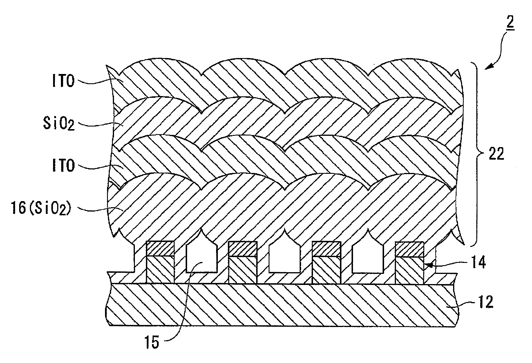
AI Technical Summary

Benefits of technology

[0010]An advantage of the present invention is to provide a wire grid type polarization element that has resistance to a rubbing treatment and suppresses deterioration of its optical characteristics, and a manufacturing method of the same. Another advantage of the invention is to provide a liquid crystal device and an electronic apparatus provided with such polarization element and therefore having high display-quality and high reliability.
[0011]A polarization element according to a first aspect of the invention includes: a base; a plurality of metal thin wires provided on the base along a predetermined alignment axis; and a plurality of protection films covering each of the plurality of metal thin wires. In the element, each of the protection films covers an upper end and both sidewalls of one of the metal thin wires. Further, a width of a part, which is on the upper end of the one of the metal thin wires, of the each of the protection films in a direction of the alignment axis is larger than a width obtained by summing a width of the one of the metal thin wires in the direction of the alignment axis and widths of parts, which are on the both sidewalls of the one of the metal thin wires, of the each of the protection films in the direction of the alignment axis. The protection films on sidewalls, which are opposed to each other, of the metal thin wires that are adjacent form an air gap.
[0012]According to the polarization element having such structure, the upper end and the both sidewalls of the metal thin wires are reinforced by the protection films, being able to prevent the metal thin wires from being damaged. Further, the width of the part, which is on the upper end of the metal thin wires, of the each of the protection films is larger than the width of the metal thin wires, so that the protection films narrow an upper part of space formed between the metal thin wires that are adjacent. Therefore, in a case where other material is deposited on the metal thin wires as well, the protection films can prevent deposited substance from entering the space formed between the metal thin wires. Accordingly, the space between the metal thin wires is not filled, providing the polarization element having excellent optical characteristics.
[0013]It is preferable that parts, which are on upper ends of the metal thin wires that are adjacent, of the protection films contact with each other in a direction parallel to the direction of the alignment axis.
[0014]According to the structure, the parts, which are on the upper ends of the metal thin wires that are adjacent, of the protection films contact with each other, so that an air gap in which air can be sealed (or that can be vacuumed) is formed. Therefore, the polarization element having excellent optical characteristics can be obtained.
[0015]It is preferable that a plurality of deposited films be formed on a surface, which is not face the air gap, of the parts, which are on the upper ends of the metal thin wires that are adjacent, of the protection films so as to form a protection layer.

Problems solved by technology

However, the metal thin wires provided to the wire grid type polarization element are too fragile to be damaged even by slight contact, being very hard to be handled.
In this rubbing treatment, the metal thin wires may be disadvantageously damaged.
Therefore, if gaps between the metal thin wires are completely filled with a protection material such as transparent resin for protecting the polarization element, the optical characteristics may be deteriorated.
However, the method disclosed in the first and second examples has such problem that the thickness of the whole of the polarization element is increased because of the transparent substrate used as the protection member for the metal thin wires.
In a case of building the polarization element in a liquid crystal device, the thickness of the protection film disadvantageously prevents the device to be thinned.
Further, the method disclosed in the third example employs a sputtering method by which a film is slowly formed, so that it takes long period of time to form the protection film having enough thickness.
In addition, in the method, the upper surface of the metal thin wires is protected but the metal thin wires themselves are not reinforced, so that the wires are damaged in the rubbing treatment described above.
If the reaction progresses, a space between the metal thin wires becomes narrow at an extent of the thickness at which the protection films grow, making hard for a material gas to go between the metal thin wires.
If the protection films preferentially grow at the upper ends of the metal thin wires, it becomes furthermore harder for the material gas to go between the metal thin wires.

Method used


Image

  • Polarization element, method for manufacturing the same, liquid crystal device, and electronic apparatus
  • Polarization element, method for manufacturing the same, liquid crystal device, and electronic apparatus
  • Polarization element, method for manufacturing the same, liquid crystal device, and electronic apparatus

Examples


working examples

[0096]Results of an evaluation on intensity of a polarization element with respect to rubbing will be described as a working example of the invention.

[0097]To a sample (CVD sample) evaluated in the working example, a protection film was formed under the following reaction conditions of the CVD method: gas flowing amount of TEOS / O2=12 / 388 sccm, pressure of 40 Pa, reaction temperature of 110° C., and reaction time of 2 minutes. A film forming rate of the protection film was 103 nm / min. As a comparative example, a polarization element in which a protection film having a similar film thickness was formed by sputtering (sputter sample) was evaluated. The reaction conditions under the sputtering were the following: gas flowing amount of Ar / N2=30 / 7 sccm and reaction time of 60 minutes. A film forming rate of the protection film was 2.2 nm / min.

[0098]Intensity was evaluated such that a polyimide film is formed on each of the sample polarization elements that were prepared and rubbing treatme...


PUM

PropertyMeasurementUnit
Thicknessaaaaaaaaaa
Widthaaaaaaaaaa
aaaaaaaaaa

Abstract

A polarization element includes: a base; a plurality of metal thin wires provided on the base along a predetermined alignment axis; and a plurality of protection films covering each of the plurality of metal thin wires. In the element, each of the protection films covers an upper end and both sidewalls of one of the metal thin wires. Further, a width of a part, which is on the upper end of the one of the metal thin wires, of the each of the protection films in a direction of the alignment axis is larger than a width obtained by summing a width of the one of the metal thin wires in the direction of the alignment axis and widths of parts, which are on the both sidewalls of the one of the metal thin wires, of the each of the protection films in the direction of the alignment axis.The protection films on sidewalls, which are opposed to each other, of the metal thin wires that are adjacent form an air gap.

Description

BACKGROUND[0001]1. Technical Field[0002]The present invention relates to a polarization element, a method for manufacturing the same, a liquid crystal device, and an electronic apparatus.[0003]2. Related Art[0004]Liquid crystal devices are used as an optical modulator of various electro-optic devices. Such structure of liquid crystal devices are widely known that a liquid crystal layer is sandwiched in between a pair of substrates that are disposed in an opposed manner. The devices are commonly provided with a polarization element and an alignment film. The polarization element allows predetermined polarized light to enter the liquid crystal layer, and the alignment film controls an alignment of liquid crystal molecules when no voltage is applied.[0005]As a polarization element, a film type polarization element and a wire grid type polarization element are known. The film type polarization element is manufactured such that a resin film is extended in one direction so as to align com...

Claims


Application Information

Patent Timeline
IPC IPC(8): G02B5/30G02F1/1335B05D5/06
CPCG02F2001/133548G02B5/3058G02F1/133548
Inventor KUMAI, YOSHITOMO
Owner SEIKO EPSON CORP
Learn More