Light Transmission Panels, Retaining Clip and a Combination Thereof

a technology of light transmission panels and retaining clips, which is applied in the direction of building roofs, roofing, building components, etc., can solve the problems of negative uplift forces, enlarging the space between these lower interior ends, and glazing panels to be pulled off, so as to improve the retention effect and increase the load

Inactive Publication Date: 2009-02-26
VIKON LLC
View PDF53 Cites 32 Cited by
  • Summary
  • Abstract
  • Description
  • Claims
  • Application Information

AI Technical Summary

Benefits of technology

[0008]In the embodiment having two connectors, the internal connector cooperates with the clip connector to hold the panels together and thereby decrease the gap between lower internal ends of the seam flanges as compared to the conventional retention systems that lack an internal as well as external connector. In those embodiments, which may lack the internal connector, the lowering of the hinge point also results in an improved retention of the external connector and a decrease in the gap between adjacent interior glazing panel ends as compared to the higher hinge points of the conventional systems having a retention clip.
[0009]When using a combination of internal and external connectors, the internal connector may be made stronger than the external connectors that it may better resist bending and flexing thereof with high uplift loads as compared to the external connector. The internal connector may also be made with a tolerance that allows the connected upstanding seam flange to expand with increases in temperature of the glazing panel which expands at a rate corresponding to its coefficient of expansion. The external connector may have less tolerance between it and its connected seam flanges, and because it is more flexible, the legs of the external connector may flex with expansion of the glazing panels under increasing temperatures being applied to the glazing panels. This tighter connection between the seam flanges and the flexible portions of the external connector allows expansion and contraction of the glazing panel while at the same time providing a weatherproof function while the less tight internal connector is performing its function of resisting uplift loads without having to perform the weatherproofing function of the external connector. The dual connectors each cover the seam between seam flanges to provide a good waterproofing of the seam to water trying to infiltrate through the seam. Thus, the use of internal and external connectors allows separation of the primary functions of weatherproofing the seam and retention of the panels under high uplift loads.
[0015]In accordance with embodiments disclosed herein, the panel ends may be joined and the seam flanges spaced from one another with the panel ends joined by clip connectors in a manner that the seam flanges are not abutting one another. This allows the seam flange and the U-connector to flex jointly, at similar angles, resulting in improved retention under increased loads.

Problems solved by technology

More specifically, high winds flowing across very large surfaces exert negative uplift forces on the panels which tend to separate the panels from one another and the retention clips as well as the battens are required to retain the glazing panel structure intact despite such forces.
This vacuum or negative pressure caused by high winds flowing over the glazing panels with a pressurized interior of the building can cause the glazing panels to be pulled off unless the clips and panels are sufficiently strong to resist the forces being generated.
In the glazing panel systems without a retention clip, the enlarging space between these lower interior ends of the glazing panels tends to break the engagement of the toothed surfaces on the upstanding seam flanges and depending legs of the inverted channel seam covering connector which covers the seam between adjacent panels.
Thus, at loads greater than that for which the glazing panel system is rated, the glazing panels separate and may be lifted from the purlins and rafters resulting in a failure of the glazing panel retention systems.

Method used


Image

  • Light Transmission Panels, Retaining Clip and a Combination Thereof
  • Light Transmission Panels, Retaining Clip and a Combination Thereof
  • Light Transmission Panels, Retaining Clip and a Combination Thereof

Examples


Embodiment Construction

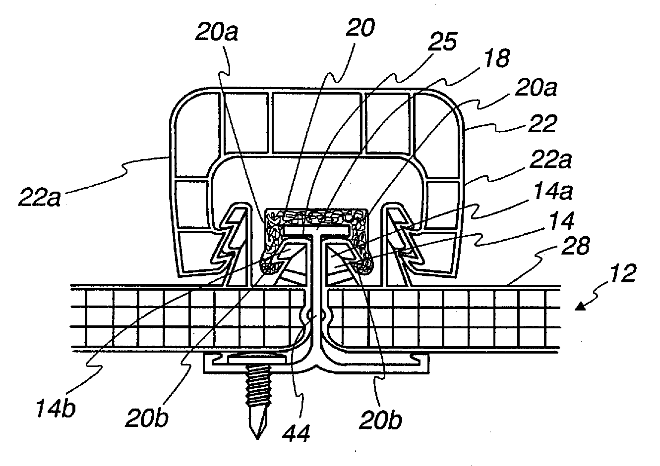
[0066]As is shown in the drawings for purposes of illustration, a glazing panel system 10 is shown in FIG. 3 as including modular extruded, glazing panels 12 that have a generally rectangular shape with upstanding projecting seam flanges 14 extending on either side of the glazing panels along their length. The preferred panel members 12 are preferably extruded and are formed with upper and lower sheets or surfaces 28 and 30 which are connected by an internal supporting structure which is shown herein in the form of ribs 32 but may have other shapes as disclosed in the aforementioned patents. Alternatively, solid plastic panel members having a solid plastic cross-section without any interior spaces or ribs may be used. The ribs 32 extend transverse to the flat sheets 28 and 30. The glazing panels are made of materials that allow light transmission therethrough such as transparent or translucent plastics, although the plastics could be opaque colored or otherwise tinted. The upstandin...


PUM


Abstract

A glazing panel system is provided with improved glazing panels, retention clips and / or U-shaped connectors. The retention clip may engage the glazing panels at locations lower than top ends of the upstanding seam flanges. In one embodiment, an internal U-shaped connector is positioned to engage the seam flanges while an external U-shaped connector covers the internal connector and the seam between adjacent glazing panels. The glazing panels may be formed with pockets adjacent the base of the upstanding seam flanges to receive a portion of the retention clip to apply retention forces at locations below the upper ends of the seam flanges. The retention clips may be formed with an upper transverse portion that is movable relative to the base portion of the clip to accommodate panel expansion and contraction. Also, a thicker plate or portion may be provided at a top flange for the retention clip to provide increased resistance to uplift loads trying to bend the flange.

Description

CROSS REFERENCE TO RELATED APPLICATION[0001]This application is a continuation of pending U.S. patent application Ser. No. 10 / 607,748, filed Jun. 27, 2003, which is incorporated herein by reference in its entirety.FIELD OF THE INVENTION[0002]This invention relates to a high performance architectural glazing panel system, glazing panels therefor and retention clips for retaining the glazing panels against separation particularly due to uplift loads from high velocity winds flowing over the glazing panels.BACKGROUND OF THE INVENTION[0003]As disclosed in U.S. Pat. Nos. 4,573,300 and 6,164,024, module glazing panels are used with a framing grid of purlins and rafters to form a wall, an overhead or roofing structure such as for skylights, covered walkways, pool enclosures, building atriums, greenhouses, etc. Glazing panels generally have light transmission properties to allow light to pass through the structure to illuminate interior regions covered by the glazing panels. The glazing pan...

Claims


Application Information

Patent Timeline
Patent Type & Authority Applications(United States)
IPC IPC(8): E04D3/06E04H9/14E04D3/02E04D3/366E04D3/08E04D3/28E04D3/361
CPCE04D3/08E04D3/28E04D3/366E04D2003/3615E04D2003/085E04D2003/285E04D2003/0806
Inventor KONSTANTIN, MOSHE
Owner VIKON LLC
Why Eureka
Try Eureka