Coated pipe and method using strain-hardening brittle matrix composites

a brittle matrix and composite material technology, applied in the direction of coatings, corrosion prevention, mechanical equipment, etc., can solve the problems that existing pipe claddings that rely on structural geometry or stratification can be difficult to manufacture, and achieve the effects of reducing material volume and cost, facilitating offshore applications, and facilitating shipping, construction, maintenance and disposal

Inactive Publication Date: 2009-02-05
MECC TECH
View PDF24 Cites 10 Cited by
  • Summary
  • Abstract
  • Description
  • Claims
  • Application Information

AI Technical Summary

Benefits of technology

[0009]The present invention improves upon prior-art pipe protection methods by providing a cladding material, which is damage tolerant by design, without reliance upon the structural configuration of the cladding to accommodate limited bending of the pipe.
[0011]The invention is suitable for fabrication of concrete weight coating around pipe for off-shore applications. This can be done while eliminating structural mesh reinforcement through dispersed fiber reinforcement and reducing the product cost significantly by uniformly doping the reinforced fiber cladding with heavyweight fillers, such as metal powders, etc.
[0012]According to one aspect of the invention there is provided a pipe of any size diameter, which is then coated with an impact, and abrasion resistant cladding material that is isotropic and inherently damage tolerant by nature. The cladding material does not rely on stratified layers of reinforcing mesh embedded within concrete or other brittle cementitious matrices for impact resistance, fracture toughness, or crack width control.
[0013]In the preferred embodiments, the cladding material is based upon a fiber-reinforced matrix, cementitious in nature for certain applications, which demonstrates pseudo-strain-hardening behavior in uniaxial tension with random orientation of fibers within the composite to provide impact and abrasion resistance. This cladding material possesses which tensile ductility to allow bending of the coated pipe without causing large cracks or disintegration through cladding material fracturing.
[0015]The protective cladding layer may be of any thickness, and of any density provided that the material is isotropic and inherently damage tolerant. However, thinner cladding configurations of lightweight material are preferred to facilitate shipping, construction, maintenance, and disposal of the pipeline sections, and to reduce material volume and cost. In some applications the cladding may be configured as heavyweight material to facilitate offshore applications. In this case, heavyweight fillers (i.e. non-reactive in nature) may be used to increase the density of the heavyweight, pseudo-strain-hardening, and fiber reinforced matrix. The material may be formulated for lightweight applications, with densities even below that of water (typically 1,000 kg / m3), while heavyweight versions of the cladding material range from 2200 kg / m3 (the density of common concrete) or less up to 4000 kg / m3 or more.
[0016]According to another aspect of the present invention, there is provided a structural configuration integrated within the impact-resistant cladding for protective housing of in-line leakage and failure monitoring technology. The present invention relies on optical sensing technology integrated into the pipe system for continuous or intermittent sensing of pipeline leakage or failure. According to the invention, a side path can be easily fabricated upon the top of the protective coating (or cladding) for housing the sensing cable along the pipe. With this pre-built side path along the pipeline, sensing cable can be installed quickly and protected effectively, and easily accessed later on for maintaining services.

Problems solved by technology

As pipe diameters become exceedingly large or small, existing pipe claddings that rely on structural geometry or stratification can be difficult to manufacture.

Method used


Image

  • Coated pipe and method using strain-hardening brittle matrix composites
  • Coated pipe and method using strain-hardening brittle matrix composites
  • Coated pipe and method using strain-hardening brittle matrix composites

Examples


Embodiment Construction

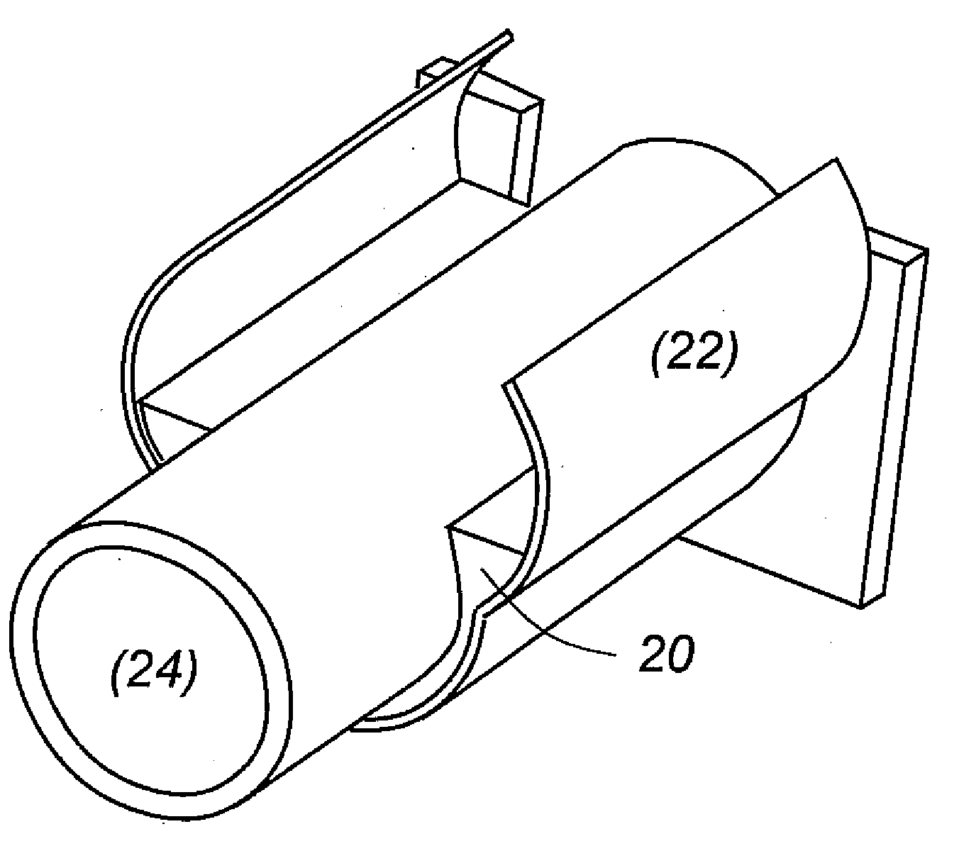
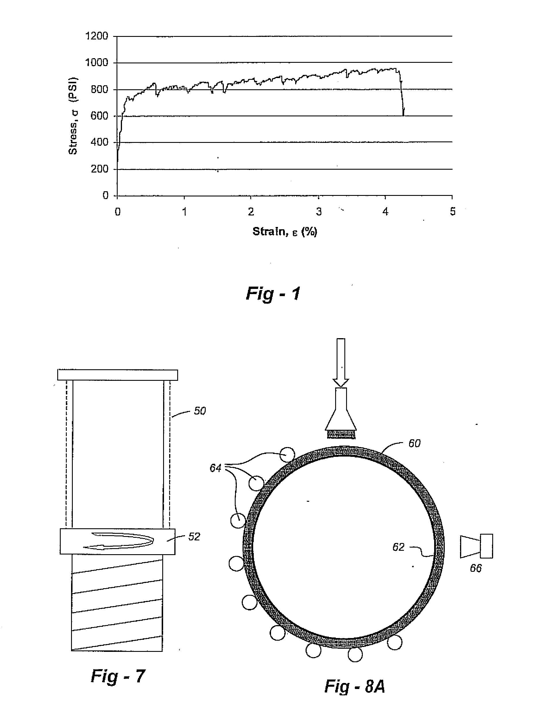
[0032]Referring to FIG. 1, the preferred embodiment of the invention uses a fiber reinforced matrix as a pipeline cladding material. This material, which is cementitious in nature for certain applications, exhibits pseudo-strain-hardening properties when loaded in uniaxial tension. Details of the material itself may be found in Li, V. C., “On Engineered Cementitious Composites (ECC)—A Review of the Material and its Applications,” J. Advanced Concrete Technology, Vol. 1, No. 3, pp. 215-230, 2003, the entire content of which is incorporated herein by reference. The pseudo-strain-hardening behavior of the preferred material is marked by forming a distribution of tightly spaced microcracks in the strain-hardening deformation range to accommodate macroscopic tensile, bending, or shear deformation without forming large localized cracks in excess of 200 μm in width.

[0033]When cementitious in nature, fiber reinforced brittle matrix composites may be formed of a mixture of cementitious mater...


PUM

PropertyMeasurementUnit
Thicknessaaaaaaaaaa
Angleaaaaaaaaaa
Densityaaaaaaaaaa

Abstract

Pipe cladding is based upon a fiber-reinforced brittle matrix composite material. The coating is isotropic, demonstrating pseudo-strain hardening behavior in uniaxial tension, and damage tolerance by design, not relying on stratified layers of reinforcing mesh embedded within concrete or other brittle cementitious matrices for impact resistance, fracture toughness, or crack width control. The fiber reinforced brittle matrix composite cladding protects both the pipe and inner thin, anti-corrosion layer (if present) from impact or abrasion damage while permitting bending of coated and clad pipe. The finished composite clad can be in a simple circular form alone the pipe or in some complex form providing an integrated housing for electrical or optical fiber cables, or optical sensing sensors for continuous or intermittent sensing of pipeline leakage or failure.

Description

FIELD OF THE INVENTION[0001]This invention relates generally to pipeline protection and, more particularly, to the use of fiber-reinforced brittle matrix inorganic composites in such applications.BACKGROUND OF THE INVENTION[0002]Metal pipes used in pipeline applications are typically coated with a layer of corrosion-resistant material, often a thin resinous layer, which serves as a barrier to penetration of water and other corrosives thereby protecting the base metal from corrosion damage. While in practice cathodic protection of the metal pipe may also be employed, this thin resinous layer is critically important to maintaining the integrity of the pipeline after installation.[0003]During the transportation and installation process, both the pipe and the anti-corrosion layer are susceptible to mechanical damage, impact, and abrasion caused by falling rock and debris during backfilling operations. To prevent this potentially disastrous damage, a protective jacket is required to prot...

Claims


Application Information

Patent Timeline
IPC IPC(8): B05D1/36
CPCF16L58/109F16L58/06
Inventor LI, VICTOR C.LEPECH, MICHAELLIU, WEIPINGDU, WEICHONG
Owner MECC TECH
Why Eureka
Try Eureka