Double seat valve

Active Publication Date: 2009-01-08
TUCHENHAGEN GMBH
View PDF6 Cites 14 Cited by
  • Summary
  • Abstract
  • Description
  • Claims
  • Application Information

AI Technical Summary

Benefits of technology

[0016]In order to achieve the object forming the base of the present invention, a first inventive basic idea includes to lead the seat cleaning flow discharging from the associated choke gap in the respective seat cleaning process into the leakage cavity possibly free of turbulence and obstructions and to discharge it from there into the surroundings in the same manner. This is achieved on the one hand by a new flow contour guiding and steering the seat cleaning flows in the leakage cavity. This new flow contour ensures in the seat cleaning of the first closing element arranged at the bottom that the first seat cleaning flow follows the wall form in the area of the first seat free of detachment. Thereafter, a smooth diversion of this first seat cleaning flow occurs in a central recess, which is provided in a front face of the cylindrical lug of the second closing element, such that the latter flow can arrive in a discharge bore centrally arranged in the first closing element without colliding and forming pressure impact thereby with the first closing element in the area of its areas bounding the leakage cavity or with the intermediate seal. The central recess is formed substantially by a rotationally symmetrical diversion area, which starts on the outside at said front face of the second closing element and which is bounded on the front side by a front face oriented substantially vertically with regard to the longitudinal axis of the second closing element, the diversion area leading into the front face.
[0027]The first inlet slope proposed by the invention facilitates the insertion of the first seal into the cylindrical first seat and reduces the wear of this seal thereby. However, with regard to fluidics this inlet slope constitutes rather a disadvantage, since it delays the first seat cleaning flow by increasing the flow cross-section and thus constitutes a detachment risk for the flow. It is proposed in this connection to provide the first end section forming the first inlet slope by at least one envelope of cone. In order to avoid detachment of the seat cleaning flow from the contour of this envelope of cone it is proposed, to bend the end section by an angle of pitch, which ranges between 0 and 15 degrees, preferably ranges between 5 to 15 degrees and is here implemented, again preferably, with 15 degrees.
[0032]In order to avoid that the first seat cleaning flow having left the diversion area flows against the intermediate seal or the front face of the recess and forms impact pressure thereby, it is further envisioned that the diversion area undercuts the front face by an axial undercutting distance. Thereby the contour of the diversion area in the area of its outlet point can be pitched by a fourth diversion angle with regard to the front face such that the first seat cleaning flow just tangents the intermediate seal, is slightly diverted thereby towards the second closing element and can then follow the wall shape of the adjacent front face of the recess in order to clean it. It has been proven as beneficial, if the fourth diversion angle is implemented in the range of 5 to 20 degrees, preferably with 15 degrees.
[0036]In order to avoid formation of turbulence and impact pressure not only in the area of the seats of the double seat valve described above, it is advantageous, if any internal fittings and obstructions in the remaining leakage cavity are omitted, as far as this is constructively possible. In this regard a further proposal envisions that a first shifting rod connected with the first closing element concentrically penetrates a second shifting rod configured as a hollow rod and connected with the second closing element, continues flying through the discharge bore and is, at an end of the first closing element averted from the second closing element, fixedly connected with the first closing element through at least one substantially radially oriented traverse. Thereby the usual struts and other connecting means otherwise usual in the area of the leakage cavity are avoided and are relocated at an end located relatively far away from the leakage cavity, where they cannot have any disturbing influences on the flow guiding any more.
[0037]In this connection is it also proposed that three traverses equally spaced across the circumference are firmly provided at a shifting rod section, which are each firmly connected radially on the outside with a circumferential ring, and that the shifting rod section, the traverses and the ring form an integral welding part. In this it is further advantageous that the welding part connects on the outside via the ring to a pressure balance piston bounding a section of the discharge bore remote from the leakage cavity and on the inside via the shifting rod section to the first shifting rod, and that the ring is enlarged in its inner diameter with regard to the diameter of the discharge bore and the intermediate arrangement of a conical expanding transition area such that the inner passage of the discharge bore is not narrowed by the traverses.
[0040]As the second seal experiences an elastic reshaping during extension from the second inlet slope, which has such an effect that is remains longer as desired in contact with the inlet slope, which obstructs flow, a further proposal envisions that the second inlet slope expands at its end directed towards the second closing element into an opening slope, the latter being pitched with regard to the second seat by an opening angle preferably in the range of 35 to 55 degrees, preferably with 45 degrees. Thereby, a desirable cross-section expansion is provided in the area of the opening slope such that the second partial lift required to ensure an unobstructed second seat cleaning flow can be reduced.

Problems solved by technology

Therefore, direct hitting by the seat cleaning flow onto the surface defining the leakage cavity is counterproductive in any case.
Such a right-angled diversion of the flow is unfavourable as a whole, it detaches uncontrollably from the wall and creates vortexes and circulation flows, which can form impact pressure.
The known configuration has a further drawback that the shape of the recess in the second closing element is determined by the shape and dimension of the cylindrical seat in the valve housing.
For this reason, there are only restricted possibilities for the fluidic design of this recess guiding and steering the seat cleaning flow.
In this case there is the risk that at least partial amounts of the second seat cleaning flow impact directly onto the sealing area of the first closing element, because the cylindrical lug forming the choke gap is missing, which is usually arranged in front of and shields this first seat seal.
Seat seals of double seat valves comprising double functions in the manner described above are not without problems, as they have to satisfy different requirements and their sphere of action is not clearly defined and limited, as it is the case with discrete seals each comprising an exclusively radial or exclusively axial / radial or exclusively axial function.

Method used


Image

  • Double seat valve
  • Double seat valve
  • Double seat valve

Examples


Embodiment Construction

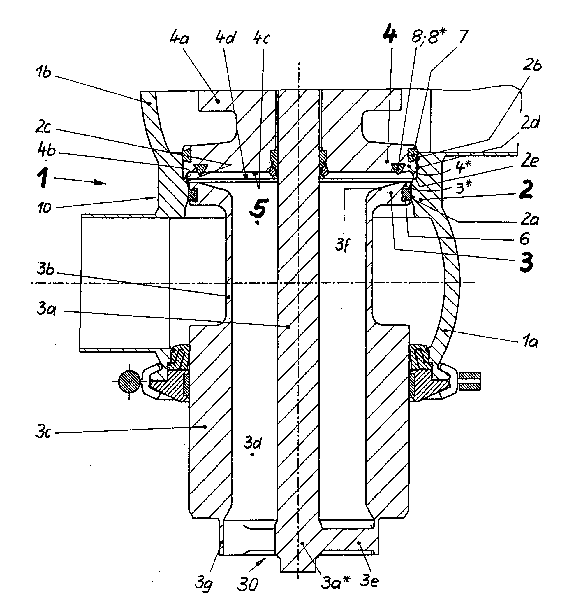
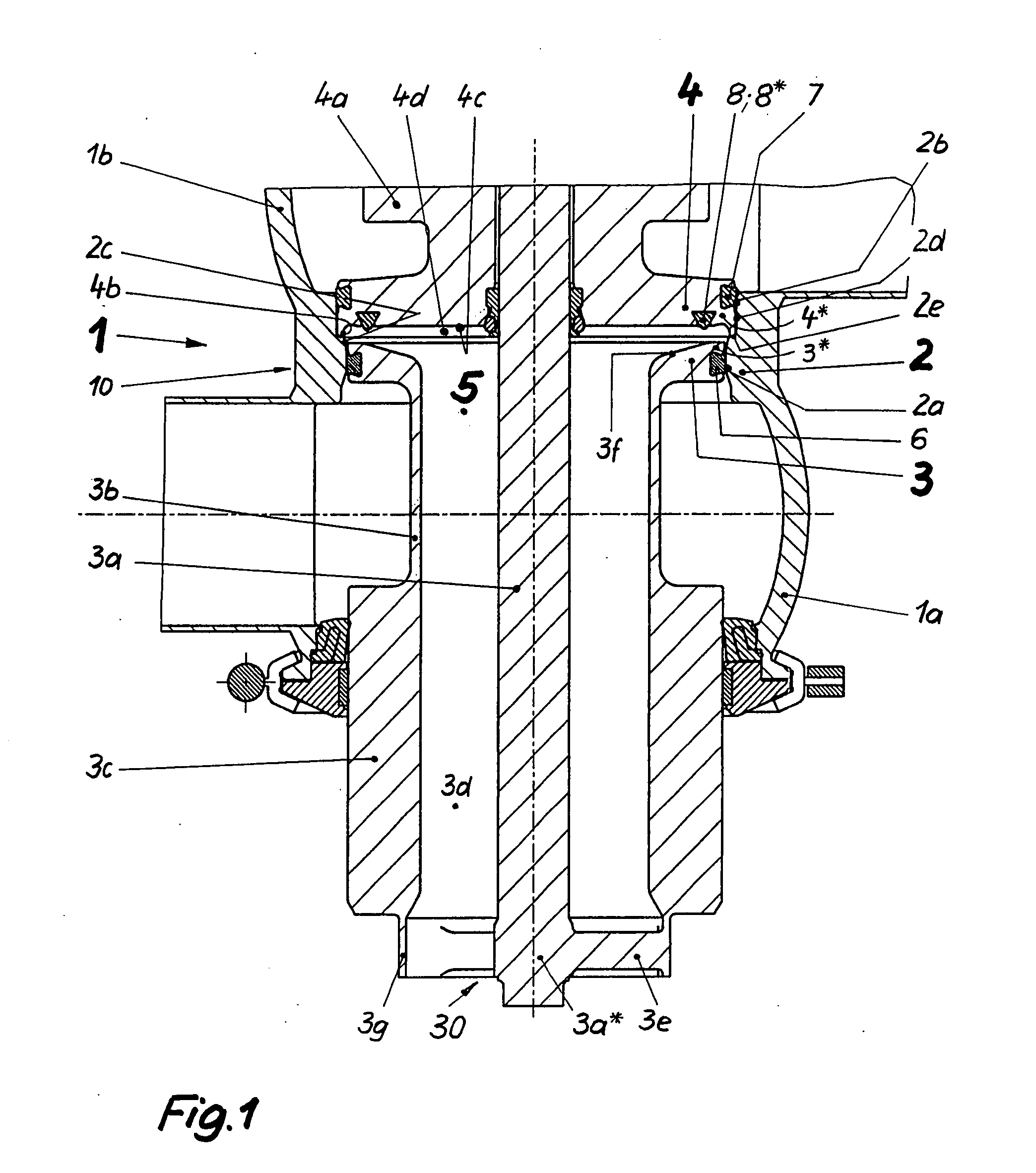
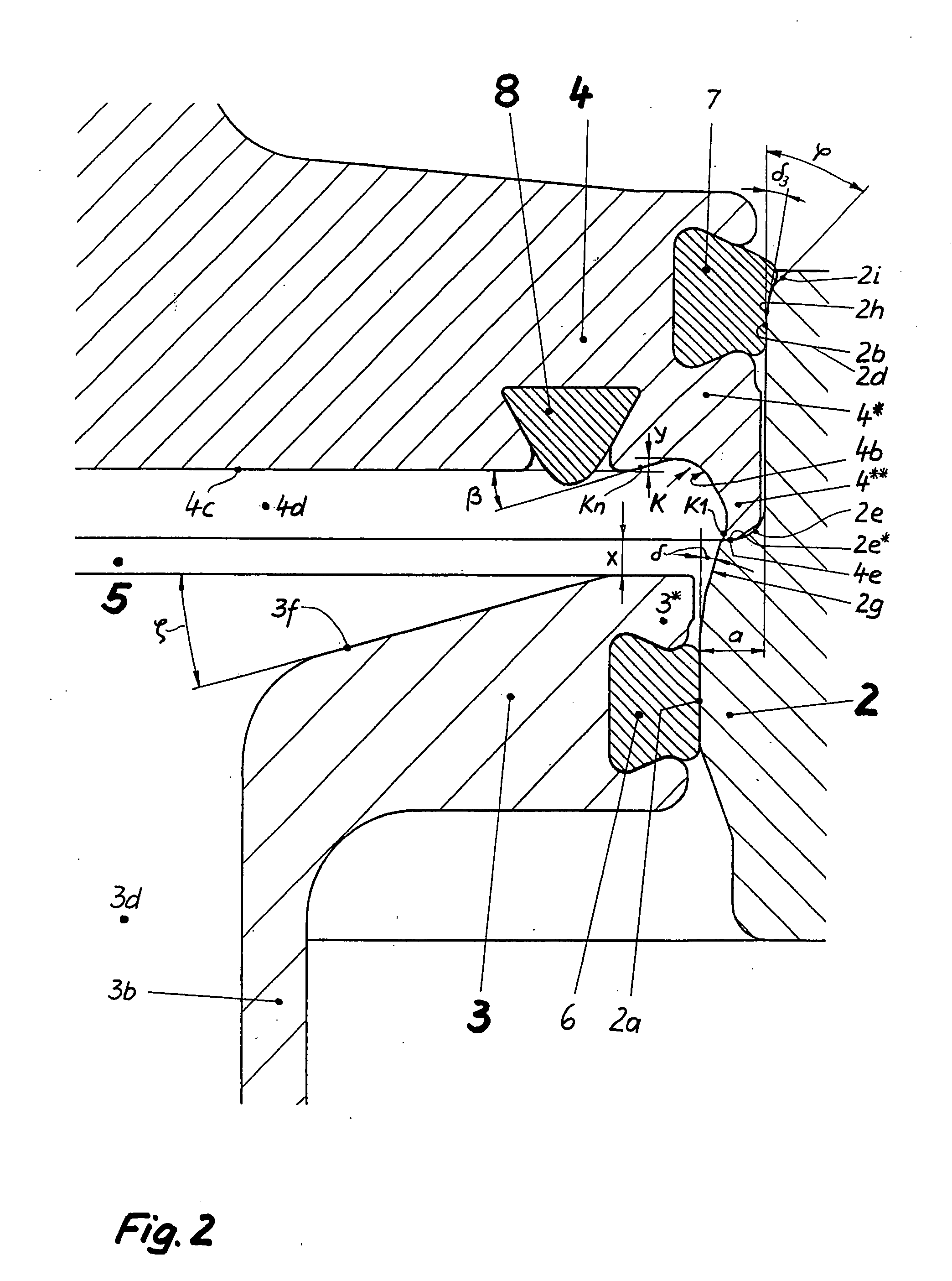
[0054]The double seat valve 1 (FIG. 1) according to the invention consists in a first embodiment substantially of the valve housing 10 comprising a first and a second valve housing part 1a and 1b, respectively, the two closing elements 3 and 4 moved independently from each other with the associated shifting rods 3a and 4a, respectively, and a seat ring 2, which creates a connection between the valve housing parts 1a, 1b through a connecting opening 2c on the inside.

[0055]The first closing element 3 formed as a slide piston (active closing element) is received in sealing manner in the closed position of the double seat valve 1 in the first seat 2a formed by the connecting opening, which is configured as cylindrical seat. For this purpose, a first seal 6 is provided in the slide piston 3, which co-operates with the first seat 2a exclusively through radial bias (radial seal with sliding engagement). The second closing element 4 also formed as a slide piston co-operates with a second se...


PUM


Abstract

The invention relates to a double seat valve with cleanable seats, which is improved with regard to the prior art in that a discharge possibly free of turbulence of the seat cleaning flow into and out of the leakage cavity is ensured and a direct admission of the seat areas, which would increase pressure, is safely avoided. This is achieved in that the second closing element (4) abuts in its closed position at the transition area (2e; 2e*) with a stop face (4e) arranged at a front face of its cylindrical lug (4*) and that directly adjacent to the first seat (2a, 2g), that a central recess (4d) is provided in the front face of the second cylindrical lug (4*), which starts radially on the outside with a rotationally symmetrical diversion area (4b) (starting point of the contour (K)) and is bounded at the front by a front face (4c) oriented substantially vertically towards the longitudinal axis of the second closing element (4), the diversion area (4b) leading out into the front face (4c) (leading out point of the contour (K)), that the diversion area (4b) and the stop face (4e) form a second circumferential edge (U2), which is directly adjacent to a first end section (2g) of the first seat (2a) in the closed position of the second closing element (4), that, viewed in vertical centre section, the diversion area (4b) comprises a contour (K) with unbent shape, wherein a direction vector in the leading out point of the diversion area (4b) points into a discharge bore (3d) centrally arranged in the first closing element (3), without colliding with the first closing element (3) in the area of its areas bounding the leakage cavity (5) or of the intermediate seal (8; 8*) and without forming impact pressure thereby, and that a frontal boundary of the first closing element (3) directed towards the leakage cavity (5) has an axial safety distance (x) from the direction vector at an outlet point of the transition area (2e) formed as a first circumferential edge (U1) into the first end section (2g).

Description

TECHNICAL FIELD[0001]The invention relates to a double seat valve comprising two closing members arranged in series and moveable with regard to each other according to the preamble of claim 1.PRIOR ART[0002]A double seat valve of the generic type, which is also designated as a double seat valve with cleanable seats due to its function, to allow cleaning of the respective seat exposed by gap-wide opening of its seats, is known from DE 196 08 792 C2. Each of the three seals in the known double seat valve is a discrete seal, wherein each seal only has one function. The first seal in the first closing element is a purely radially acting seal, which slides in the first seat formed as a cylindrical envelope and seals there as a result of the provided bias (seal with sliding engagement). The second seal in the second closing element either acts upon the conical formed second seat such that this can be designated as an axially / radially acting seal (seal with pressing engagement), or a purel...

Claims


Application Information

Patent Timeline
IPC IPC(8): F16K1/42
CPCF16K1/446Y10T137/4259Y10T137/88038Y10T137/88022
Inventor BURMESTER, JENSSUDEL, MATTHIAS
Owner TUCHENHAGEN GMBH
Why Eureka
Try Eureka