Battery electrode
a battery electrode and electrode technology, applied in the field of battery electrodes, can solve the problems of difficult to improve output according to the thickness of the active material layer, and fail to efficiently make an electrode reaction, and achieve the effect of high output and energy density
- Summary
- Abstract
- Description
- Claims
- Application Information
AI Technical Summary
Benefits of technology
Problems solved by technology
Method used
Image
Examples
first embodiment
(Structure)
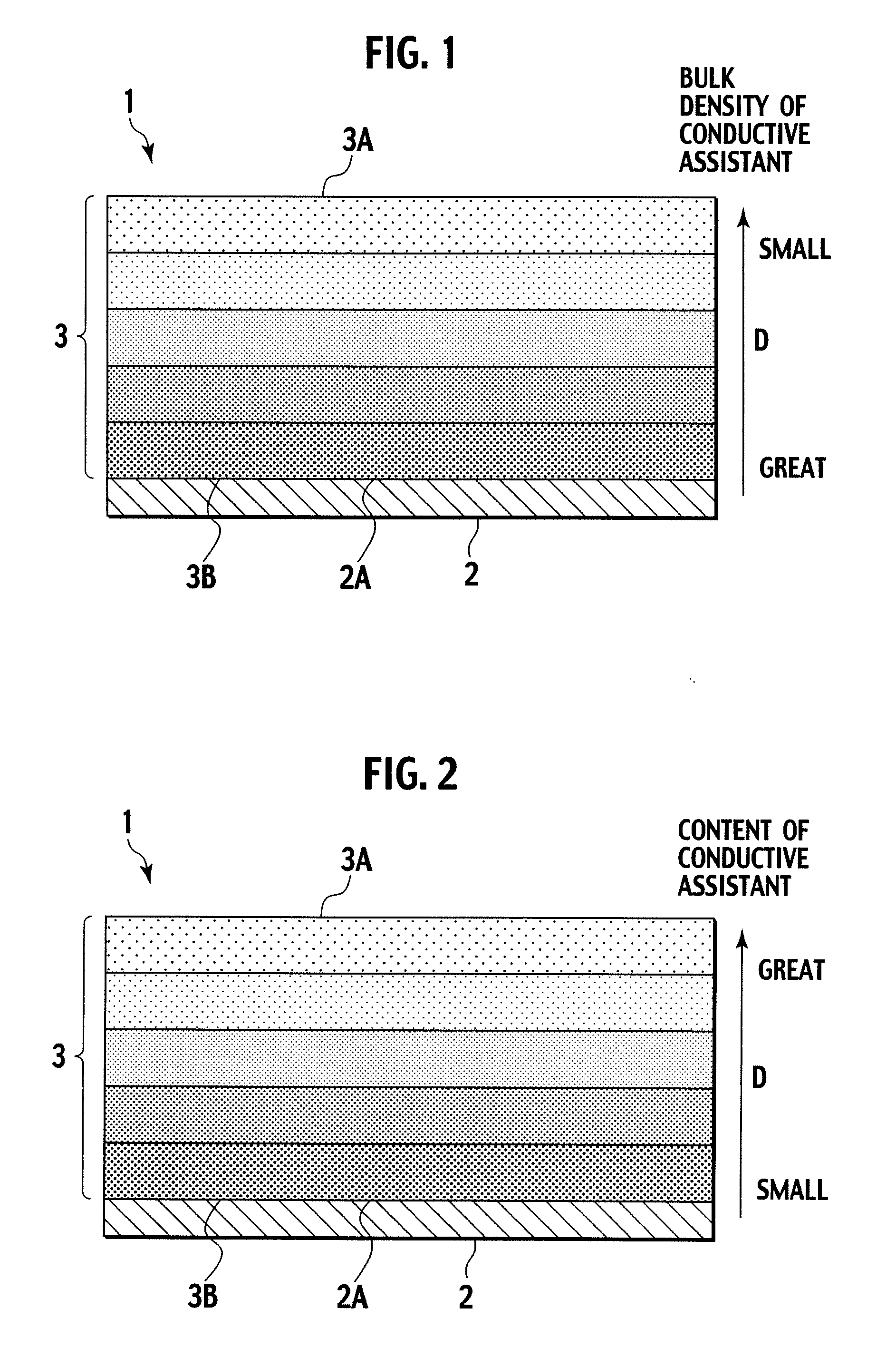
[0029]Under the present invention, a battery electrode, comprises: a collector, and an active material layer formed on a surface of the collector and including: an active material, and a conductive additive having a bulk density which is gradually decreased in a direction from a collector side of the active material layer to a surface side of the active material layer.
[0030]Hereinabove and hereinafter, an electrolyte layer including electrolyte is disposed on the surface side of the active material layer.
[0031]Hereinafter, structure of the battery electrode of the present invention is to be set forth, referring to the drawings. Under the present invention, however, drawings are emphasized for convenience sake. Therefore, the technical scope of the present invention is not limited to the embodiments in the drawings.
Moreover, an embodiment or embodiments other than those shown in the drawings may be adopted.
[0032]FIG. 1 is a schematic of a cross sectional view of a battery ...
second embodiment
[0110]According to a second embodiment, a battery is formed by using the battery electrode 1 of the first embodiment.
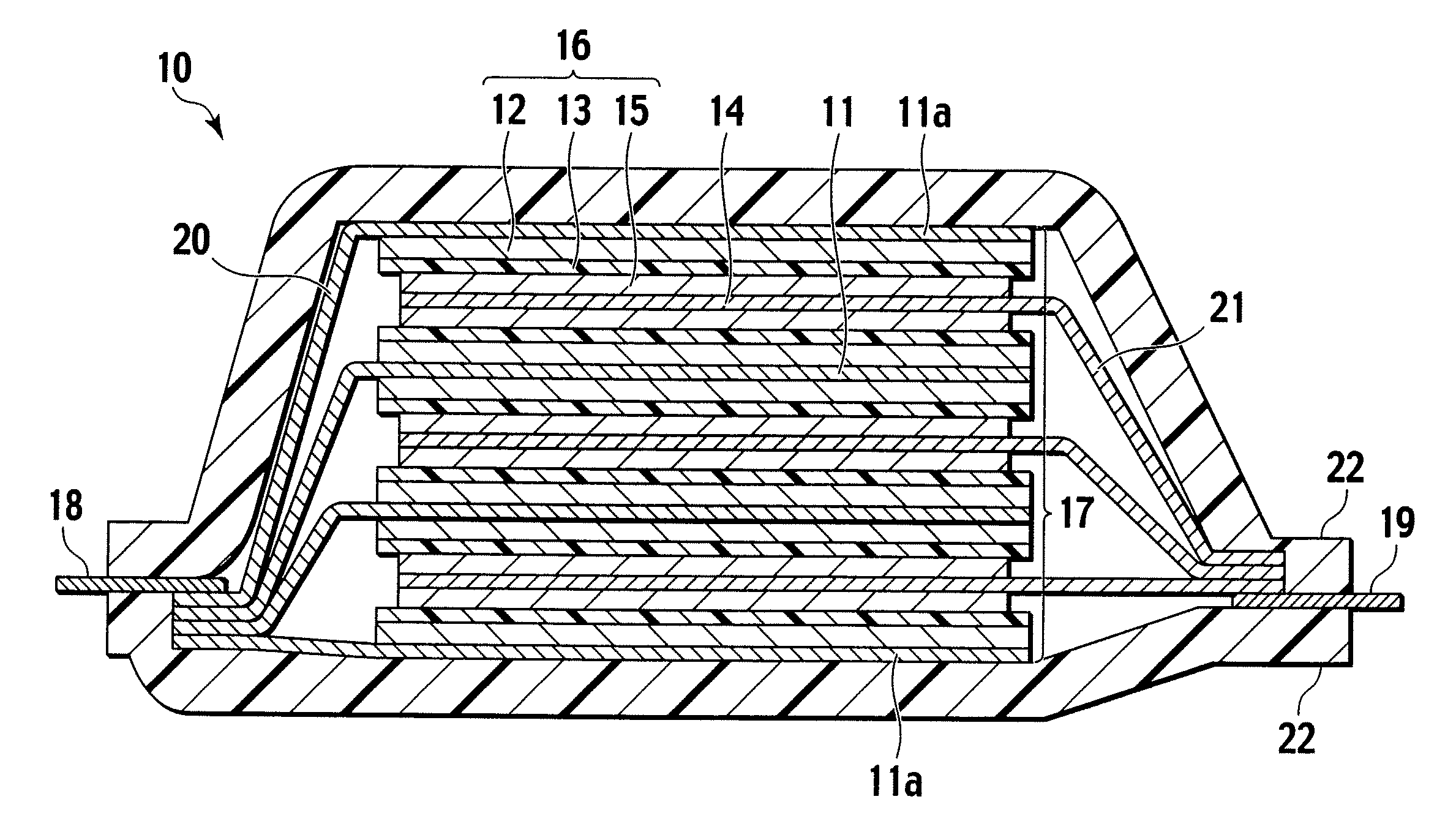
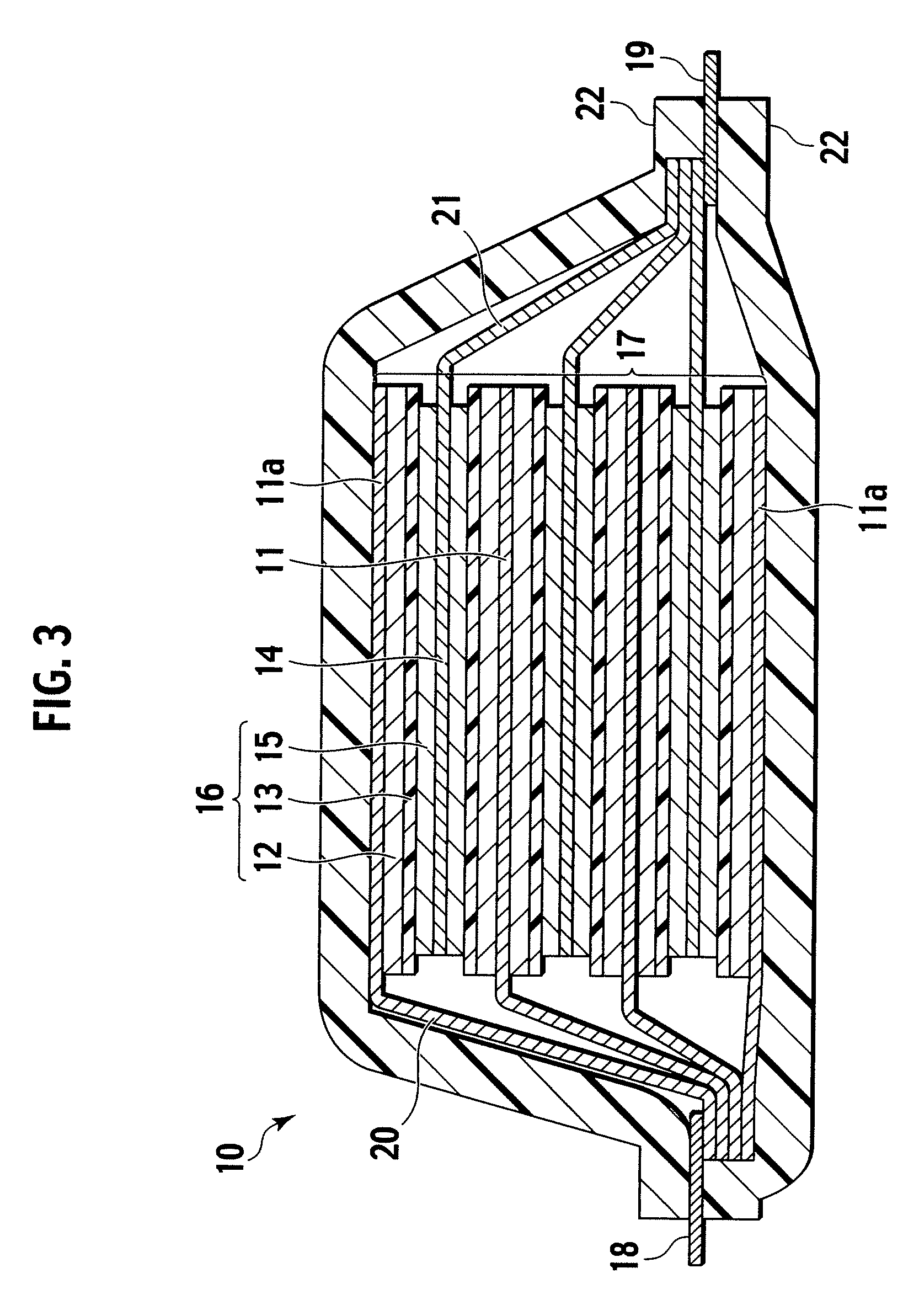
[0111]That is, according to the second embodiment, the battery includes at least one unit cell layer having such a structure that a positive electrode, an electrolyte layer and a negative electrode are sequentially stacked, wherein at least one of the positive electrode and the negative electrode is the electrode of the present invention. The electrode of the present invention is applicable to any of the positive electrode, negative electrode and a bipolar electrode. The battery including the electrode of the present invention as at least one electrode belongs to the technical scope of the present invention. It is preferable, however, that the electrode of the present invention is used to serve as all electrodes of the battery. The above structure can effectively improve cell capacity and cell output.
[0112]The structure of a secondary battery of the present invention ...
third embodiment
[0143]According to a third embodiment, the above batteries 10, 30, 40 of the respective Sections I, II, III of the second embodiment are used for forming a battery module.
[0144]A battery module of the present invention has such a structure that a plurality of lithium ion secondary batteries of the present invention are connected together, more in detail, two or more of the lithium ion secondary batteries are connected in series, parallel or both. Connecting the lithium ion secondary batteries in series or parallel can arbitrarily adjust capacity and voltage of the batteries. Otherwise, the battery module of the present invention may have such a structure that the non-bipolar lithium ion secondary battery (or batteries) and bipolar lithium ion secondary battery (or batteries) of the present invention are connected in series, parallel or both.
[0145]FIG. 6A, FIG. 6B and FIG. 6C show a typical battery module, according to the third embodiment of the present invention, where FIG. 6A is a...
PUM
| Property | Measurement | Unit |
|---|---|---|
| density | aaaaa | aaaaa |
| thickness | aaaaa | aaaaa |
| thickness | aaaaa | aaaaa |
Abstract
Description
Claims
Application Information
 - R&D
- Intellectual Property
- Life Sciences
- Materials
- Tech Scout
- Unparalleled Data Quality
- Higher Quality Content
- 60% Fewer Hallucinations
Browse by: Latest US Patents, China's latest patents, Technical Efficacy Thesaurus, Application Domain, Technology Topic, Popular Technical Reports.
© 2025 PatSnap. All rights reserved.Legal|Privacy policy|Modern Slavery Act Transparency Statement|Sitemap|About US| Contact US: help@patsnap.com


