
Separator for fuel cell and its manufacturing method and fuel cell stack using the separator

a technology of graphite separator and fuel cell, which is applied in the direction of cell components, sustainable manufacturing/processing, and final product manufacturing, etc., can solve the problems of high cost, increased stack volume, and difficulty in mass-producing polymer electrolyte membrane fuel cells having high-density graphite separators, etc., to achieve convenient manufacturing and small size

Inactive Publication Date: 2008-12-25
SAMSUNG SDI CO LTD
View PDF4 Cites 16 Cited by
  • Summary
  • Abstract
  • Description
  • Claims
  • Application Information

AI Technical Summary

Benefits of technology

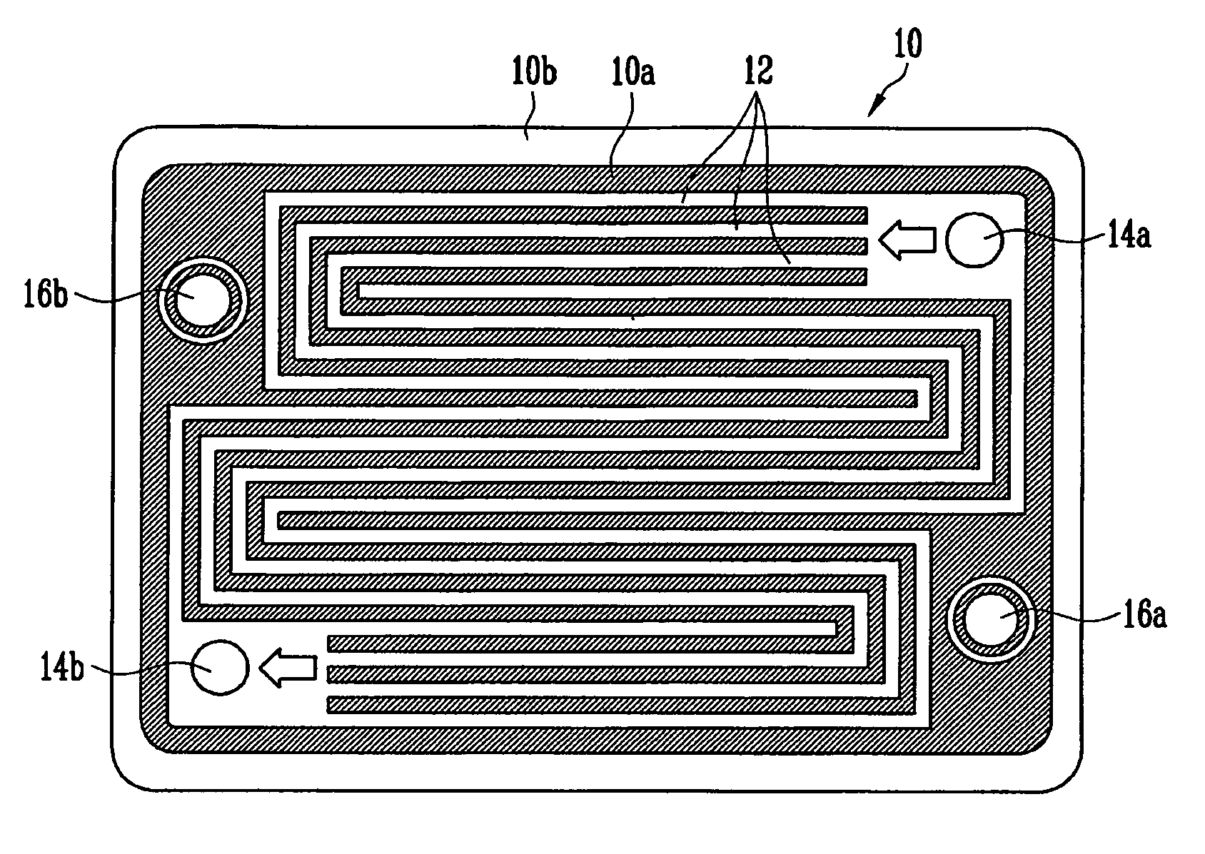
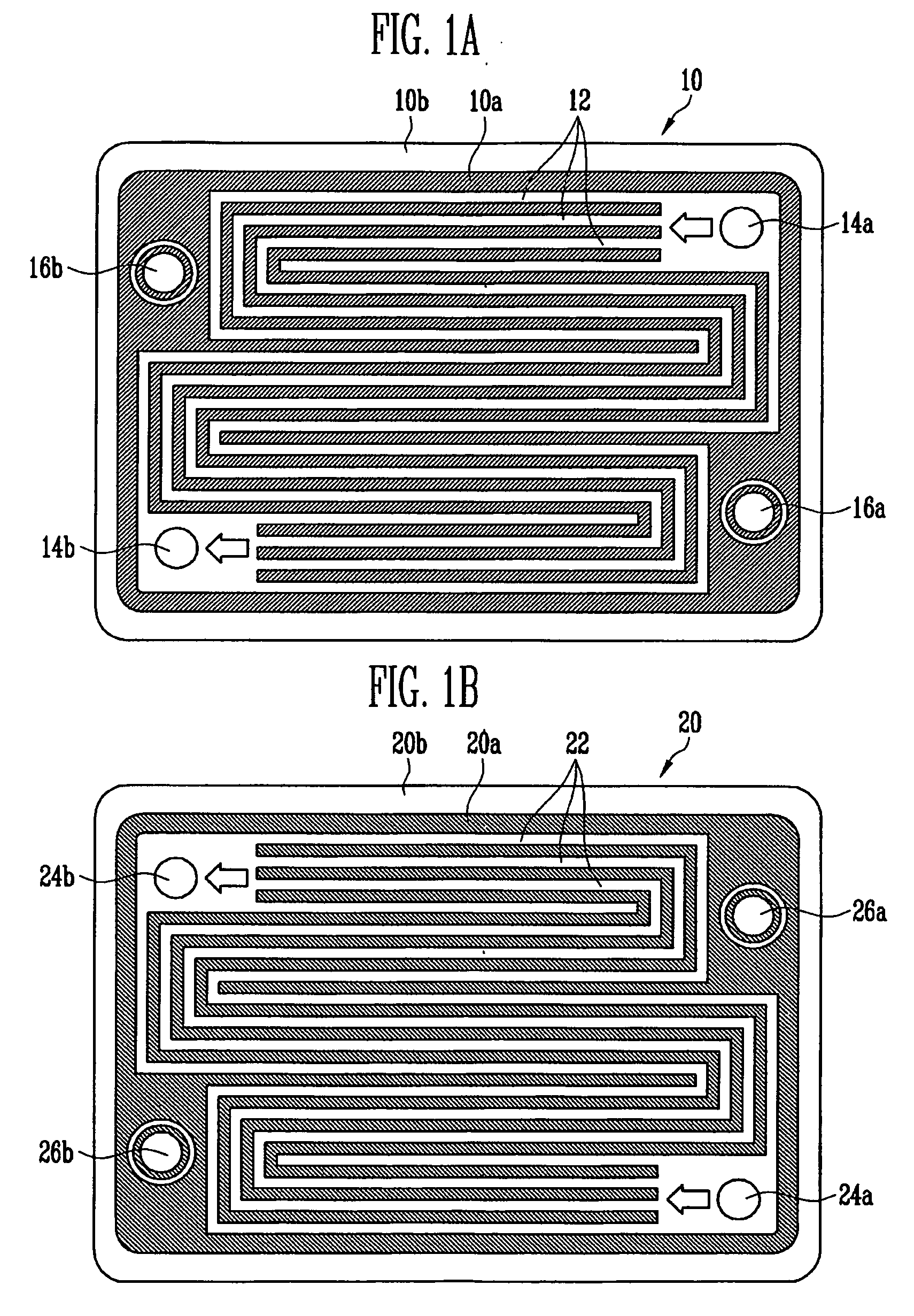
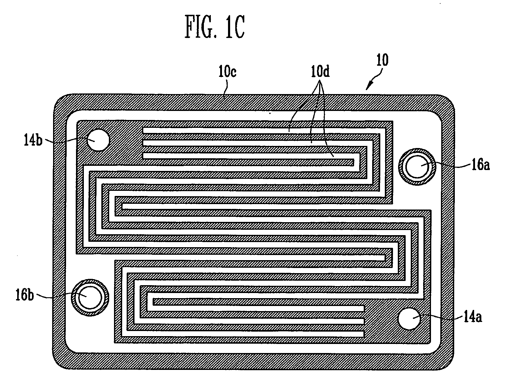
The present invention provides a metallic separator for a fuel cell that can be utilized on both sides of the plate, and a manufacturing method for it. Additionally, the invention provides an inexpensive fuel cell stack that can be easily manufactured with a small size by utilizing the metallic separator. The separator includes a plate with flow channels, inlet and outlet holes, and a bridge unit with a smaller depth at a region where the direction of flow of the inlet or outlet hole and the direction of flow of the flow channel cross. The invention also provides a method for manufacturing the separator using a first and second mold. The fuel cell includes the membrane electrode assembly with the anode electrode, cathode electrode, and electrolyte, and the metallic separator on the surface of the membrane electrode assembly. The technical effects of the invention include improved fuel cell performance, reduced size of the fuel cell stack, and simplified manufacturing process.

Problems solved by technology

The high-density graphite can be manufactured to form a light-weight stack because it has good electric conductivity and high corrosion resistance, and also has a low density due to the presence of numerous inner pores, but it has a problem in that the stack has to be relatively thick to prevent (or block) mixing of reaction gases, which leads to an increased volume of the stack.
Also, the high-density graphite has disadvantages in that it needs to be subjected to an expensive machining process when it is being molded, which accounts for at least 60% of the manufacturing cost of the polymer electrolyte membrane fuel cell, and it is difficult to mass-produce the polymer electrolyte membrane fuel cell having the high-density graphite separator.

Method used


Image

  • Separator for fuel cell and its manufacturing method and fuel cell stack using the separator
  • Separator for fuel cell and its manufacturing method and fuel cell stack using the separator
  • Separator for fuel cell and its manufacturing method and fuel cell stack using the separator

Examples


Embodiment Construction

[0026]In the following detailed description, only certain exemplary embodiments of the present invention are shown and described, by way of illustration. As those skilled in the art would recognize, the invention may be embodied in many different forms and should not be construed as being limited to the embodiments set forth herein. Also, when a first element is referred to as being “on” a second element, it can be directly on the second element or be indirectly on the second element with one or more intervening elements interposed there between. In addition, when a first element is described as being “coupled to” a second element, the first element may be not only directly coupled to the second element but may also be indirectly coupled to the second element via one or more intervening elements. Further, elements that are not essential to the complete understanding of the invention may be omitted for clarity. Like reference numerals designate like elements throughout the specificat...


PUM

PropertyMeasurementUnit
temperatureaaaaaaaaaa
thicknessaaaaaaaaaa
thicknessaaaaaaaaaa

Abstract

A separator for a fuel cell, including: a plate; a first flow channel having a first depth on a first side of the plate; a first inlet hole coupled to the first flow channel; a first outlet hole coupled to the first flow channel; a second flow channel on a second side of the plate; a second inlet hole coupled to the second flow channel; a second outlet hole coupled to the second flow channel; and a bridge unit having a second depth less than the first depth at a region where a direction of flow of at least one of the first inlet hole or the first outlet hole and a direction of flow of the second flow channel cross.

Description

CROSS-REFERENCE TO RELATED APPLICATION[0001]This application claims priority to and the benefit of Korean Patent Application No. 10-2007-0059974, filed on Jun. 19, 2007, in the Korean Intellectual Property Office, the entire content of which is incorporated herein by reference.BACKGROUND[0002]1. Field of the Invention[0003]The present invention relates to a separator for a fuel cell that is pressed into a single plate and employs a bidirectional flow channel, its manufacturing method, and a fuel cell stack using the separator.[0004]2. Discussion of Related Art[0005]A fuel cell is a power generation system for producing electrical energy through an electrochemical reaction of an oxidant and a fuel (e.g., a hydrocarbon-based fuel). A fuel cell can be a molten carbonate fuel cell (MCFC), a solid oxide fuel cell (SOFC), a polymer electrolyte fuel cell (PEFC), a phosphoric acid fuel cell (PAFC), an alkaline fuel cell (AFC), etc., depending on the kind of electrolytes being utilized.[0006...

Claims


Application Information

Patent Timeline
Patent Type & Authority Applications(United States)
IPC IPC(8): H01M2/14H01M2/00H01M8/10
CPCH01M8/0206H01M8/0228H01M8/0254H01M8/026H01M8/0263H01M8/0265H01M2008/1095Y02P70/56Y10T29/49108Y02P70/50Y02E60/50H01M8/02
Inventor LEE, JAE-WOOKLEE, KEUN-YONGPARK, CHAN-HEE
Owner SAMSUNG SDI CO LTD
Learn More