
Fiber optic gyroscope with integrated light source

a fiber optic gyroscope and light source technology, applied in the field of optical polymer waveguides, can solve the problems of time-consuming and complicated prior art process, and achieve the effects of less potential for error, less cost, and short fabrication tim

Inactive Publication Date: 2008-11-27
LITTON SYST INC
View PDF9 Cites 21 Cited by
  • Summary
  • Abstract
  • Description
  • Claims
  • Application Information

AI Technical Summary

Benefits of technology

[0004]Fabrication of a doped polymer waveguide should prove to be simpler, have shorter fabrication time, have less potential for error and be less costly than fabrication of prior art waveguides.

Problems solved by technology

The prior art process is time consuming and requires many steps in which process errors could occur.

Method used


Image

  • Fiber optic gyroscope with integrated light source
  • Fiber optic gyroscope with integrated light source
  • Fiber optic gyroscope with integrated light source

Examples


Embodiment Construction

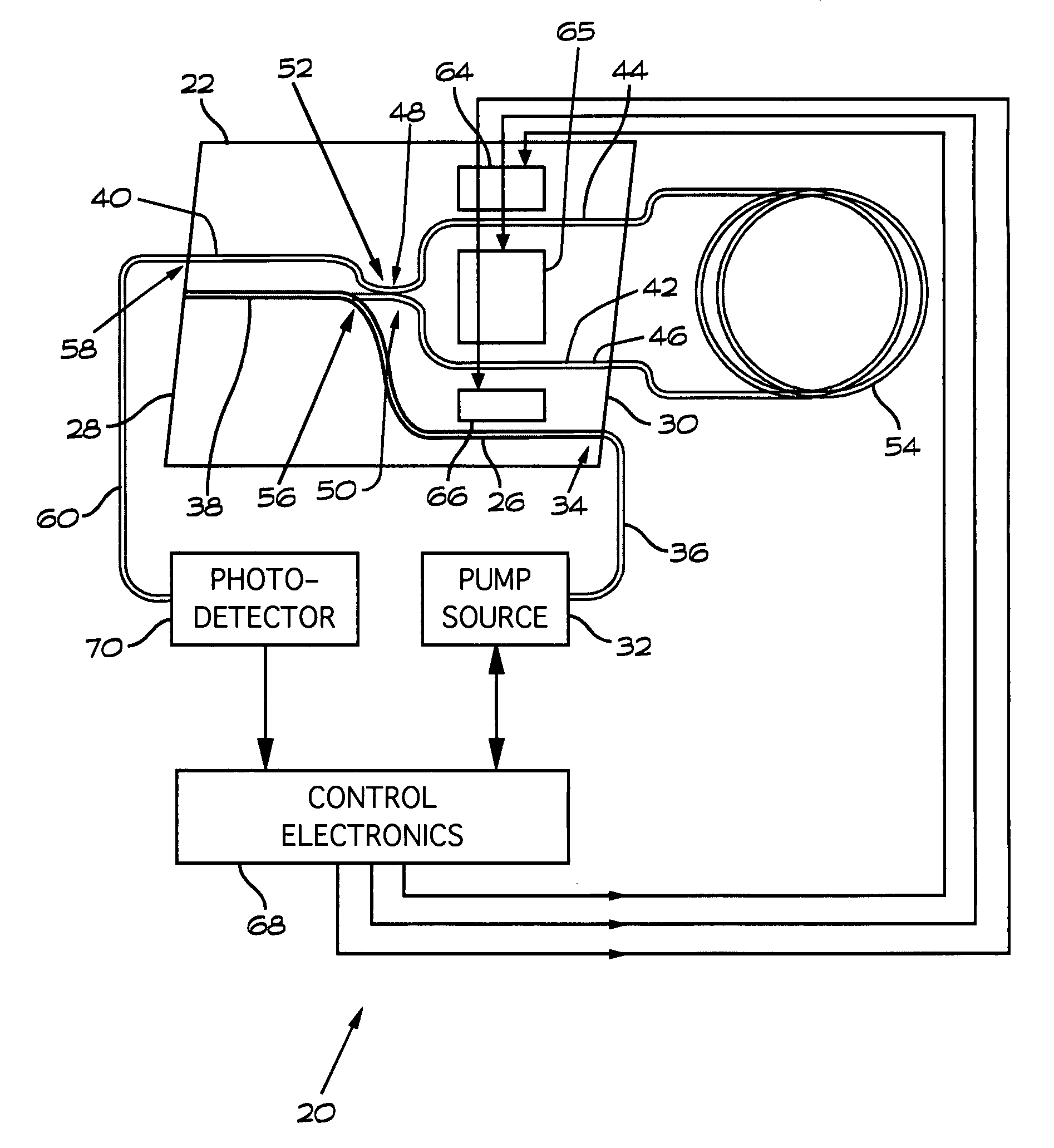
[0019]Referring to FIG. 1, a fiber optic gyroscope 20 includes a module 22 formed on a polymer substrate 24. A first portion of the polymer substrate 24 is doped with a rare earth material to form a rare earth doped polymer waveguide (REDPW) 26. The REDPW 26 extends across the substrate 24 between opposite edges 28 and 30 thereof. A pump light source 32 is connected to an end 34 of the REDPW 26 by an optical fiber 36. The pump light interacts with the REDPW to form an amplified spontaneous emission (ASE) light source 38.

[0020]Second and third portions of the substrate 24 are doped to form optical waveguides 40 and 42. The optical waveguides 40 and 42 have portions 44 and 46, respectively, that are preferably parallel. The optical waveguides 40 and 42 also have portions 48 and 50, respectively, that converge together to form an optical coupler 52.

[0021]The parallel portions 44 and 46 of the optical waveguides 40 and 42, respectively, are optically coupled to a fiber optic sensing coi...


PUM


Abstract

An integrated module for a fiber optic gyroscope system includes a fiber optic sensing coil arranged to sense rotations about a sensing axis via the Sagnac effect comprises a substrate, an optical waveguide formed on the substrate, a light source comprising a doped waveguide formed on the substrate. The light source and the optical waveguide are arranged to produce counterpropagating light waves in the fiber optic sensing coil. The light source may be formed as a rare earth doped polymer waveguide or as a rare earth doped glass waveguide.

Description

BACKGROUND OF THE INVENTION[0001]This invention relates generally to optical waveguides and particularly to optical polymer waveguides and the use of such waveguides in fiber optic rotation sensor systems.[0002]Optical fibers doped with rare earth ions such as erbium, praseodymium and neodymium are well-known. Optical amplifiers, superfluorescent light sources and fiber lasers have been fabricated using doped fiber technology. Fabrication of prior art waveguides requires that the waveguide be formed in an optically transparent substrate. Rare earth ions are then diffused into the waveguide region of the substrate. The prior art process is time consuming and requires many steps in which process errors could occur.SUMMARY OF THE INVENTION[0003]This invention uses rare earth doped optical polymer waveguides and modulators. Advantages of this over other doped waveguides are in the method of fabrication and the close index of refraction match to that of the optical fiber.[0004]Fabricatio...

Claims


Application Information

Patent Timeline
Patent Type & Authority Applications(United States)
IPC IPC(8): G01C19/72
CPCG01C19/721
Inventor MEYER, A. DOUGLASYAHALOM, RAM
Owner LITTON SYST INC
Learn More