
Non-Aqueous Electrolyte Battery

a non-aqueous electrolyte, battery technology, applied in secondary cells, electrochemical generators, cell components, etc., can solve the problems of low battery voltage, insufficient charge-discharge capacity, and inability to discharge from the positive electrode current collector, etc., to achieve the effect of increasing the capacity of the battery, reducing the energy density, and dramatically increasing the electronic conductivity

Active Publication Date: 2008-11-20
SANYO ELECTRIC CO LTD
View PDF13 Cites 11 Cited by
  • Summary
  • Abstract
  • Description
  • Claims
  • Application Information

AI Technical Summary

Benefits of technology

[0059]With the above-described two constructions, the same advantageous effects as described with claims 11 and 12 can be attained.
[0060]According to the present invention, good conductive paths form in the positive electrode without lowering the energy density in the positive electrode and the electronic conductivity dramatically increases; therefore, an increased capacity in a battery is achieved and discharge performance at high rate is dramatically improved.

Problems solved by technology

In contrast, the olivine-type lithium phosphate shows a low degree of adherence with a metal foil that serves as a positive electrode current collector and therefore has a problem that it can peel off from the positive electrode current collector even when a binder agent is mixed therein.
Moreover, the olivine-type lithium phosphate has a higher electrical resistance than conventionally-used materials such as LiCoO2, LiNiO2, LixNi1−yCoyO2, LiMn2O4, and LiNi1 / 3Co1 / 3Mn1 / 3O2, and therefore, when performing a charge-discharge operation at a large current, battery voltage lowers and sufficient charge-discharge capacity cannot be obtained.
In order to solve this problem, various techniques have been studied, such as coating carbon on the surface of the olivine-type lithium phosphate to enhance conductivity, but satisfactory results have not been attained.

Method used


Image

  • Non-Aqueous Electrolyte Battery
  • Non-Aqueous Electrolyte Battery
  • Non-Aqueous Electrolyte Battery

Examples


embodiments

First Embodiment

Comparative Example 1

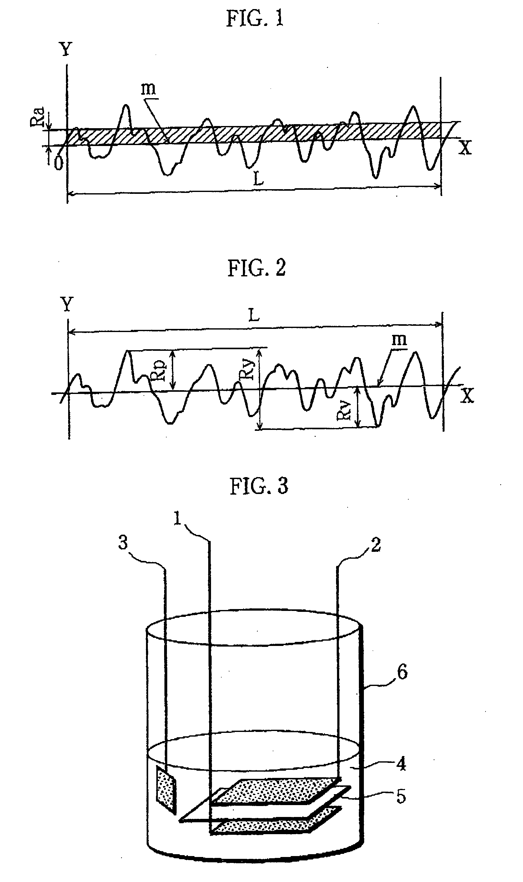
[0076]A positive electrode and a test cell were prepared in the same manner as in Example except that the positive electrode current collector used was formed of an aluminum foil that was not subjected to a blasting process for roughening and had a surface roughness Ra of 0.026 μm (Ra=0.026 μm), a maximum height Rmax of 0.59 μm (Rmax=0.59 μm), and a thickness of 15 μm.

[0077]The positive electrode and the test cell thus prepared are hereinafter referred to as Comparative Positive Electrode x1 and Comparative Cell X1, respectively.

Comparative Example 2

[0078]A positive electrode and a test cell were prepared in the same manner in Example except that a positive electrode current collector formed of an aluminum foil subjected to a blasting process for roughening, with surface roughness Ra of 0.28 μm (Ra=0.28 em), the maximum height Rmax of 4.4 μm (Rmax=4.4 μm), and the thickness of 30 μm, was used.

[0079]The positive electrode and the test cell thus pr...

experiment 1

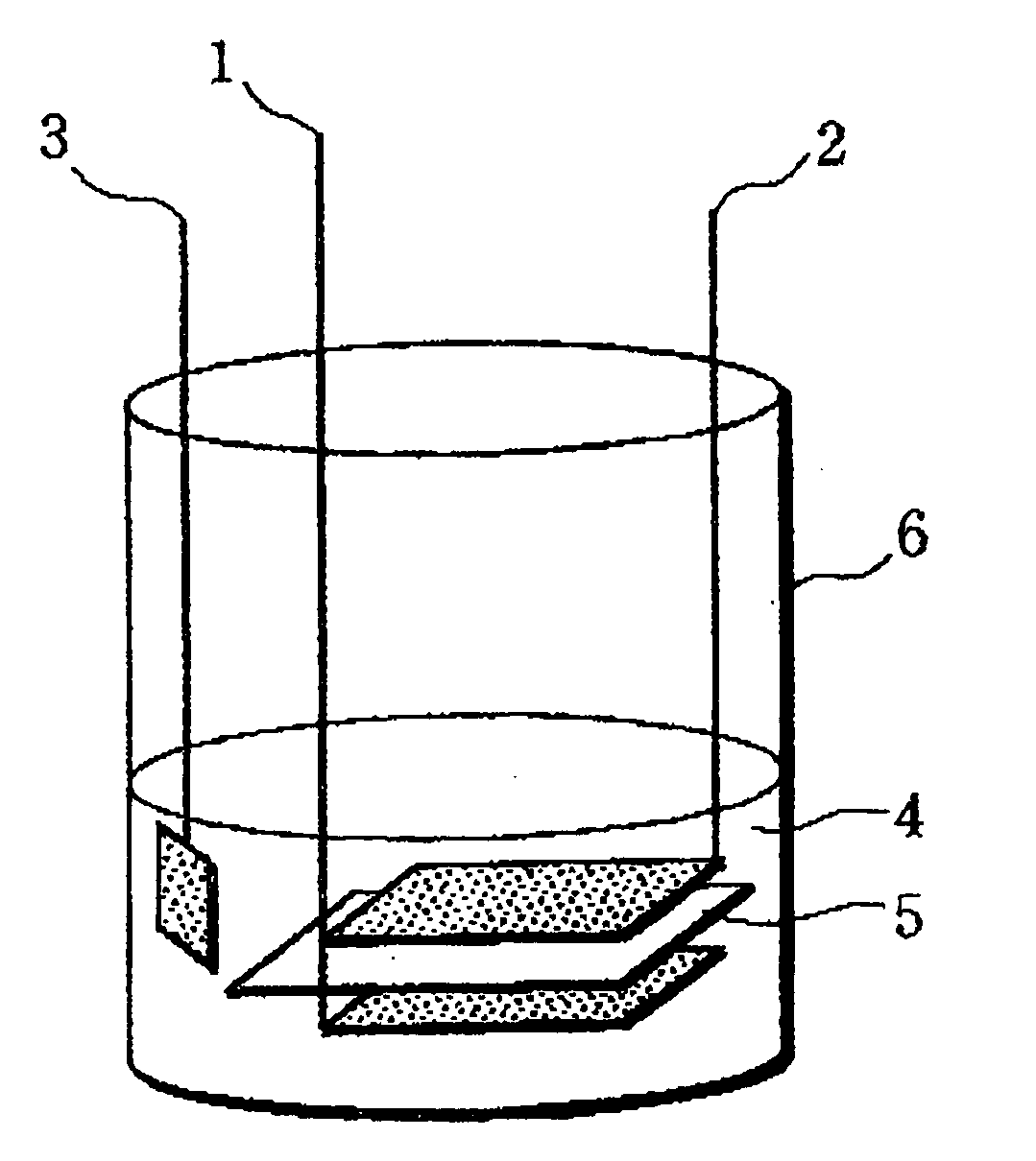
[0080]Using the foregoing Cell A of the invention and Comparative Cells X1 and X2, the discharge capacities per 1 g of the active material (mAh / g) were found at discharge current rates of 0.1 It, 0.2 It, 0.5 It, 1.0 It, and 2.0 It. The results are shown in Table 1. The charge-discharge conditions were as follows.

Charge-Discharge Conditions in the Case of a Discharge Current Rate was 0.1 It

—Charge Condition

[0081]The cells were charged at a charge current rate of 0.1 It until the cell voltage reached 4.5 V.

Discharge Condition

[0082]The cells were discharged at a discharge current rate of 0.1 It until the cell voltage reached 2.0 V.

[0083]By charging and discharging the cells under the above-noted conditions, the discharge capacities per 1 g of the active material (mAh / g) in 0.1 It discharge were found from the discharge durations at the first cycle.

Charge-Discharge Conditions in the Case of a Discharge Current Rate of 0.2 It

[0084]After the foregoing charge-discharge operation with a di...

experiment 2

[0102]Based on the results of the foregoing Experiment 1, the volumetric capacity densities of Positive Electrode a of the invention and Comparative Positive Electrodes x1 and x2 were calculated according to Equation (3) below. The results are shown in Table 2.

Volumetric capacity density (mAh / ml)=Discharge capacity per 1 g of the positive electrode active material×(Mass of the positive electrode active material / Mass of the positive electrode mixture)×(Filling density of active material)×(Thickness of positive electrode active material-containing layer / Total thickness of positive electrode)  Eq. (3)

[0103]Here, for example, in the 1.0 It discharge of Positive Electrode a of the invention, the discharge capacity per 1 g of the positive electrode active material was 124.7 (mAh / g); the mass of the positive electrode active material / the mass of the positive electrode active material-containing layer=90 / 100; the filling density of the active material was 2.2 g / mL; and the thickness of the ...


PUM


Abstract

A non-aqueous battery with improved volume energy density and enhanced load characteristics is made available even when using olivine-type lithium phosphate as a positive electrode active material.The non-aqueous electrolyte battery of the present invention is provided with a positive electrode (1) containing lithium iron phosphate as a positive electrode active material, a negative electrode (2), and a non-aqueous electrolyte (4). In the positive electrode (1), a positive electrode active material-containing layer that is made of the positive electrode active material, a conductive agent, and a binder agent is formed on a positive electrode current collector. The positive electrode current collector has a thickness of less than 20 μm and its surface that is in contact with the positive electrode active material-containing layer has a mean surface roughness Ra of greater than 0.026.

Description

TECHNICAL FIELD[0001]The present invention relates to a non-aqueous electrolyte battery comprising a positive electrode containing lithium iron phosphate as its positive electrode active material, a negative electrode, and a non-aqueous electrolyte. More particularly, the invention relates to improvements in a positive electrode current collector in which its adherence with the positive electrode active material has been enhanced.BACKGROUND ART[0002]Rapid advancements in size and weight reductions of mobile information terminals such as mobile telephones, notebook computers, and PDAs in recent years have created a demand for higher capacity batteries as driving power sources for such devices. With their high energy density and high capacity, non-aqueous electrolyte secondary batteries, such as represented by lithium-ion secondary batteries, are widely utilized as the driving power sources for such mobile information terminals as mentioned above.[0003]A non-aqueous electrolyte second...

Claims


Application Information

Patent Timeline
IPC IPC(8): H01M4/58H01M4/136H01M4/62H01M4/66H01M4/70H01M10/052H01M10/36H01M10/44
CPCH01M4/136H01M4/5825H01M4/625H01M4/661H01M4/70H01M10/052H01M10/44Y02E60/122Y02T10/7011Y02E60/10H01M4/13H01M4/485H01M4/66H01M10/058Y02T10/70
Inventor INOUE, TAKAODONOUE, KAZUNORIYU, DENIS YAU WAIFUJIMOTO, MASAHISAFUJITANI, SHIN
Owner SANYO ELECTRIC CO LTD
Learn More