
High power LED lighting assembly incorporated with a heat dissipation module with heat pipe

a technology of led lighting and heat dissipation module, which is applied in the direction of lighting and heating apparatus, semiconductor devices for light sources, transportation and packaging, etc., can solve the problems of high power led heat generation, critical problem of led dissipation, and low power consumption, and achieve low power consumption. , the effect of high power

Inactive Publication Date: 2008-10-16
TAMKANG UNIVERSITY
View PDF4 Cites 236 Cited by
  • Summary
  • Abstract
  • Description
  • Claims
  • Application Information

AI Technical Summary

Benefits of technology

[0006]A primary object of the present invention is to provide a high power LED lighting assembly that comprises a plurality of arrays of LED for emitting light. The LED lighting assembly provides sufficient illumination with low power consumption, which can replace conventional incandescent light bulbs and florescent light sources.
[0007]Another object of the present invention is to provide a heat dissipation module for dissipating heat. The heat dissipation module comprises at least one heat pipe for conducting heat from the heated section of the heat pipe to the cooling region which is fitted to a heat dissipation module for dissipating the heat efficiently.
[0008]A further object of the present invention is to provide a heat dissipation module for incorporating to a LED light assembly. The heat dissipation module is capable to effectively remove heat from the LEDs to the outside, and maintain the LED light assembly at an appropriate operation temperature. The arrangement of the heat dissipation module eliminates the overheating at any spots of the heat dissipation module and maintains the lighting stability of heat dissipation module.

Problems solved by technology

Practical applications currently are generally limited to low power indicator lamps, but with the active developments on high power LED technology in recent years.
However, with high power LED advancing, the heat generated by high power LED is also increased, and the dissipation of heat from LED becomes a critical problem.
During operation, the illumination of LED lamps generates hot spots of high temperature in radiating area on high power LED, and currently, no solution is provided.
This problem limits the development and applications of LED lamps.
The poor heat dissipation of hot spots results to the overheating of LED lamps.
When the junction temperature exceeds 120° C., the high temperature damages the LED lamps and leads to lower performance of LED, shorter service life, and even the peril of burnout.

Method used


Image

  • High power LED lighting assembly incorporated with a heat dissipation module with heat pipe
  • High power LED lighting assembly incorporated with a heat dissipation module with heat pipe
  • High power LED lighting assembly incorporated with a heat dissipation module with heat pipe

Examples


first embodiment

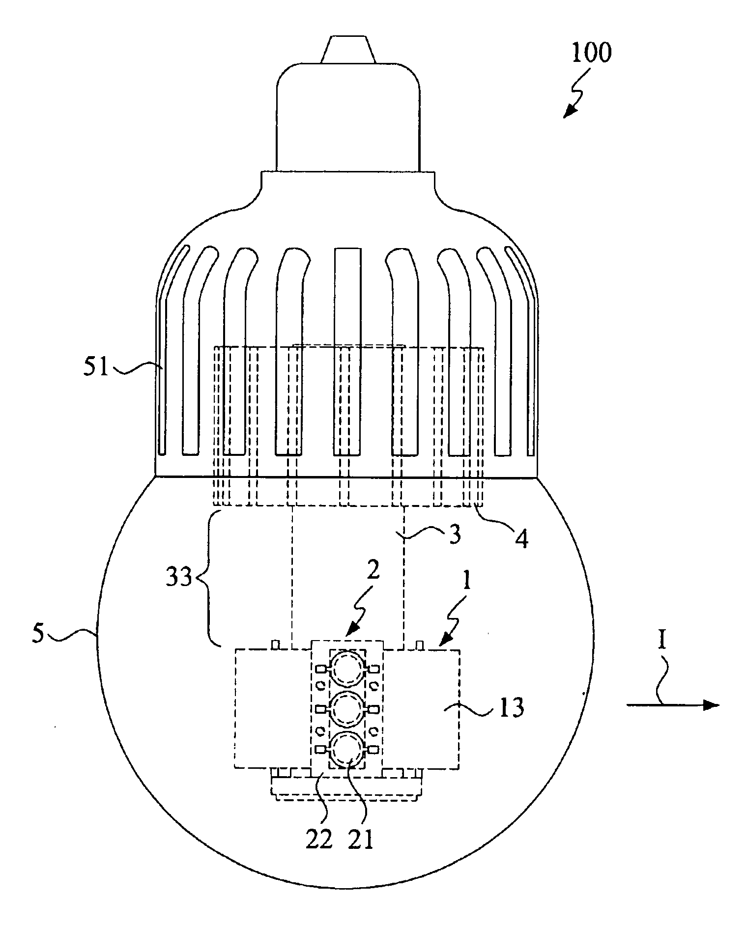
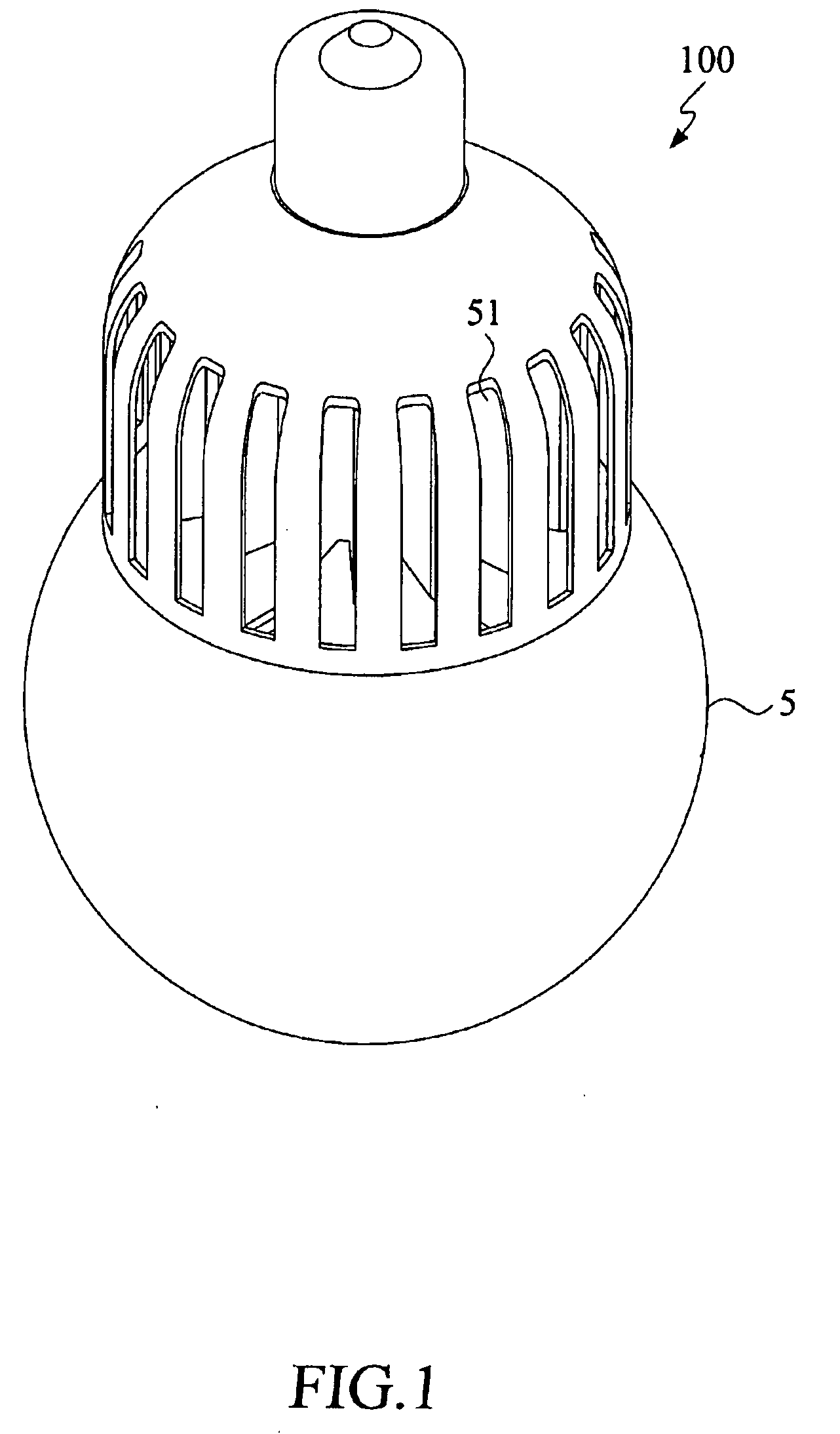
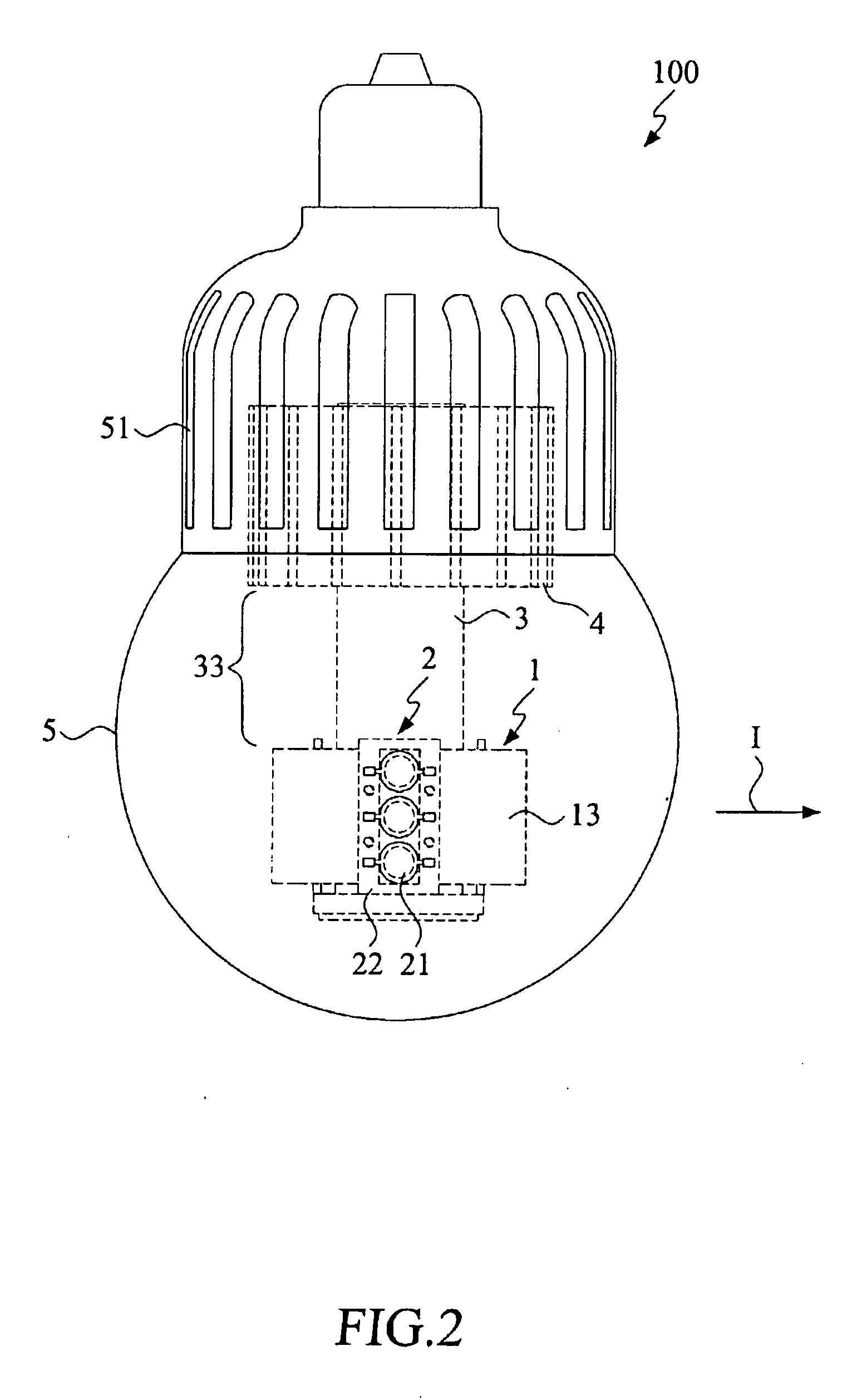
[0023]With reference to the drawings and in particular to FIGS. 1 to 3, a high power LED lighting assembly incorporated with heat dissipation module constructed in accordance with the present invention, generally designated with reference numeral 100, is shown. The high power LED lighting assembly 100 of the present invention comprises a heat exchange base 1, a plurality of LED arrays 2, a heat pipe 3, a heat dissipation module 4, and a lamp shade 5. The lamp shade 5 covers the heat exchange base 1, the LED arrays 2, the heat pipe 3 and the heat dissipation module 4, and is removable for maintenance of the components. The heat exchange base 1 is arranged at the lower part of the LED lighting assembly 100 and the heat dissipation module 4 is arranged at the upper part of the LED lighting assembly 100.

[0024]Please refer to FIGS. 4 to 8. FIGS. 4 and 5 shows the exploded schematic views of the high power LED lighting assembly after the removal of the lamp shade. FIG. 6 is a top plan vie...

second embodiment

[0034]FIG. 9 is a schematic view of the high power LED lighting assembly incorporated with a heat dissipation module constructed in accordance with the present invention, after the removal of its lamp shade. FIG. 10 is a partial exploded view of the high power LED lighting assembly of FIG. 9. FIGS. 11 and 12 show the side views of the LED lighting assembly of FIG. 9.

[0035]The second embodiment is different from the first embodiment in that the heat exchange base 1 comprising a plurality of peripheral hollow parts 12 arranged at selected location of the heat exchange base 1, while running through the top and bottom of the said heat exchange base 1. Each of the peripheral hollow parts 12 is inserted with a heat pipe 3. That is, the peripheral heat pipes 3 are arranged circularly around the central hollow part 12 of the heat exchange base 1, and each peripheral hollow part 12 is adjacent to one of the LED configuration planes 11, allowing the thermal energy generated by the LEDs 21 of ...


PUM

PropertyMeasurementUnit
temperatureaaaaaaaaaa
angleaaaaaaaaaa
thermal energyaaaaaaaaaa

Abstract

A high power light emitting diode (LED) lighting assembly incorporated with heat dissipation module is provided. The LED lighting assembly includes a heat exchange base, at least one LED array, at least one heat pipe and a heat dissipation module. The heat exchange base includes at least one LED configuration plan for mounting of the LED array and at least a hollow part for insertion of the heat pipe. The LED array is arranged at a predetermined projecting angle at the LED configuration plane. The heat pipe includes a heated section, a cooling section and a conducting section, and contains a working fluid therein. The heat exchange base is mounted to the heated section and the heat dissipation module is mounted to the cooling section. The thermal energy generated by the LEDs is conducted from the heat exchange base to the heated section of the heat pipe, whereby allowing the working fluid in the heat pipe to be heated and vaporized, and flows, from the conducting section to the cooling section for dissipation at the heat dissipation module.

Description

FIELD OF THE INVENTION[0001]The present invention relates to a design for a light emitting diode (LED) lighting assembly, and in particular to a high power LED lighting assembly incorporated with a heat dissipation module using heat pipe that is capable of dissipating heat effectively from the LED lighting assembly.BACKGROUND OF THE INVENTION[0002]According to the conclusion of Kyoto Global Climate Conference, many countries have to cut their greenhouse gas emissions to below 6% to 1990 level in years between 2008 and 1012. With the power consumption for lighting purposes accounting for more than 20% of the livelihood-based energy, the development of energy saving lighting technology becomes even more important.[0003]Light-emitting diode (LED), an optoelectronic semiconductor component that radiates by applying external voltage to simulate the electrons to produce lighting, provides the advantages of low power consumption and long service life, therefore prompting the worldwide rese...

Claims


Application Information

Patent Timeline
Patent Type & Authority Applications(United States)
IPC IPC(8): F21V29/00
CPCF21V29/004F21V29/006F21Y2101/02F21Y2111/005F21V29/83F21K9/135F21V29/506F21V29/75F21V29/777F21V3/0472F21K9/232F21Y2115/10F21Y2107/30F21V29/51F21V29/74F21V3/10
Inventor KANG, SHUNG-WENTSAI, MENG-CHANGCHIEN, KUN-CHENG
Owner TAMKANG UNIVERSITY
Learn More