Vehicle Hybrid Energy System

Active Publication Date: 2008-10-09
THE RGT OF THE UNIV OF MICHIGAN
View PDF14 Cites 39 Cited by
  • Summary
  • Abstract
  • Description
  • Claims
  • Application Information

AI Technical Summary

Benefits of technology

[0009]Embodiments of the invention offer the potential to maximize the cruising distance throughout the service. When the electric vehicle is driven in a low load state, the electric power required for driving the motor is mainly supplied from the higher energy battery among the pack to maximize the cruising distance. When the load of the electric vehicle increases and greater power is required, higher power battery will be used.
[0011]Embodiments of the invention also offer the potential to prolong the lifetime of the hybrid battery system, while accommodating demand for wide range of output power characteristics, from a low load to a high load, by charging the high gravimetric power (W / kg) battery with the electric power supplied from the high gravimetric energy (Wh / kg) battery, which always generates a constant output power. The electric power of the high power battery is used to drive the vehicle when fluctuation of the load is large, while the electric power of the high energy battery, which is capable of sustaining a constant output for a long time, is used to drive the auxiliary machines in which fluctuation of the load is small. In this manner, the possible travel distance can be extended and the size of the electric power system can be reduced. Further, the electric power system can respond to a wide range of output power demands, from a low load to a high load, and the driving characteristics can be improved.

Problems solved by technology

The design of an electrical energy storage system for an electrified drivetrain of an electric or hybrid electric vehicle poses significant challenges.
Existing vehicle electrical energy storage systems, primarily single chemistry lead-acid, nickel metal hydride, lithium and the like are inadequate.
The suggestion of a battery structure, i.e., chemistry, cell configuration, construction, size and shape, suitable for consumer electronics, for example, may not scale to provide a solution to the vehicle energy storage system designer.
A vehicle environment is also an extreme use environment subjecting the system to temperature extremes, changing temperature ranges, shock and vibration and, of course, crashes.
The typical energy storage / battery system of electric (EV), hybrid electric (HEV) or plug-in hybrid (PHEV) electric vehicle is limited to a single chemistry and cell architecture.
To meet the many diverse operating conditions the vehicle might experience, the designer necessarily compromises in selecting the battery system.
The resulting drawbacks are less than optimal energy delivery, volumetric size, weight and operating complexity (number and configuration of cells, cell monitoring for health and failure, etc.).

Method used


Image

  • Vehicle Hybrid Energy System
  • Vehicle Hybrid Energy System
  • Vehicle Hybrid Energy System

Examples


Embodiment Construction

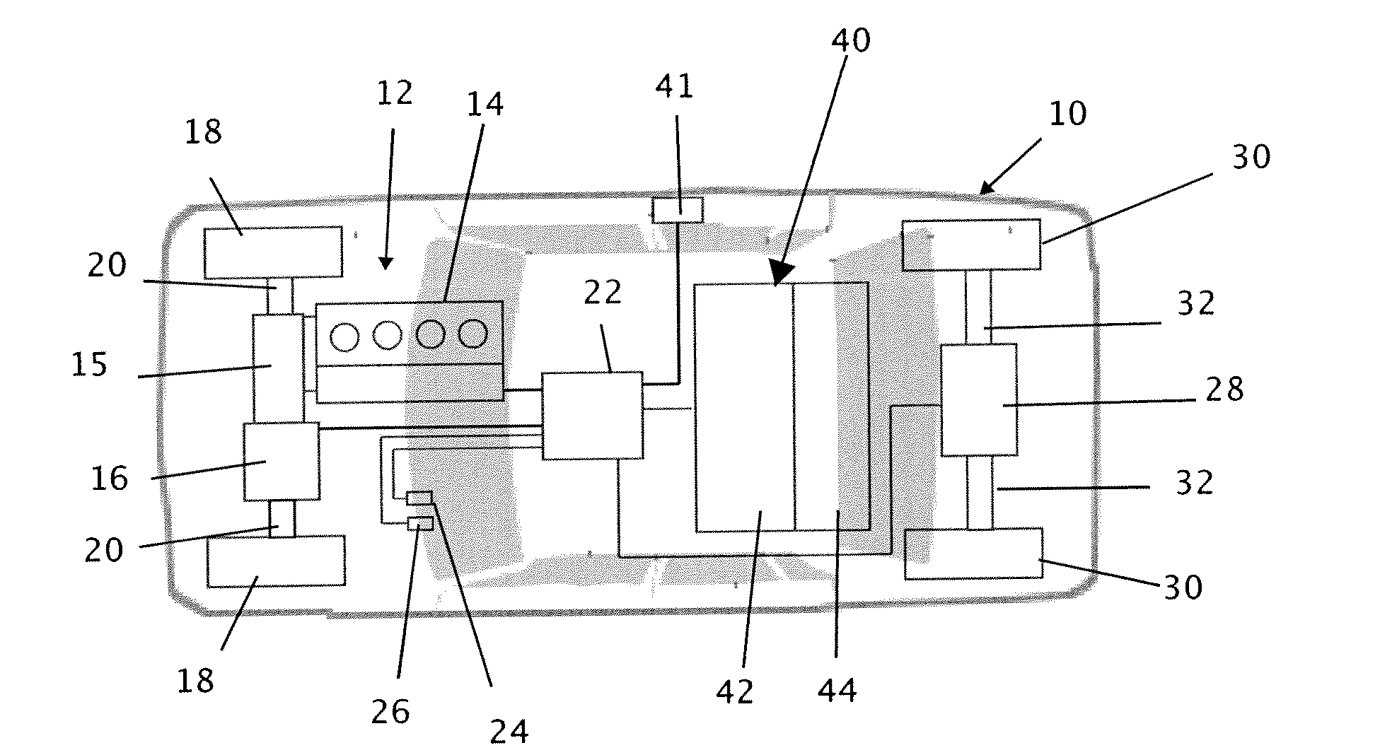
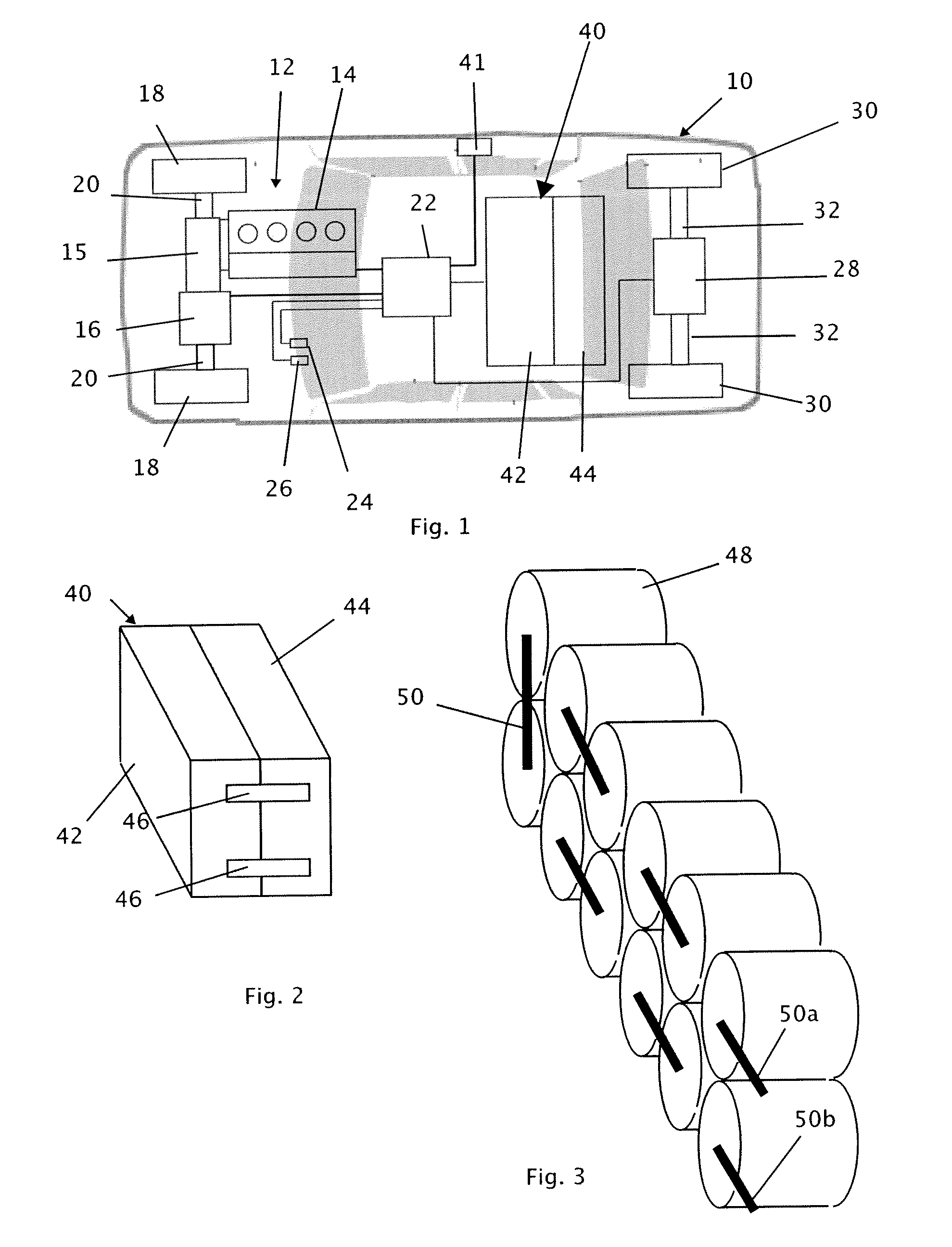
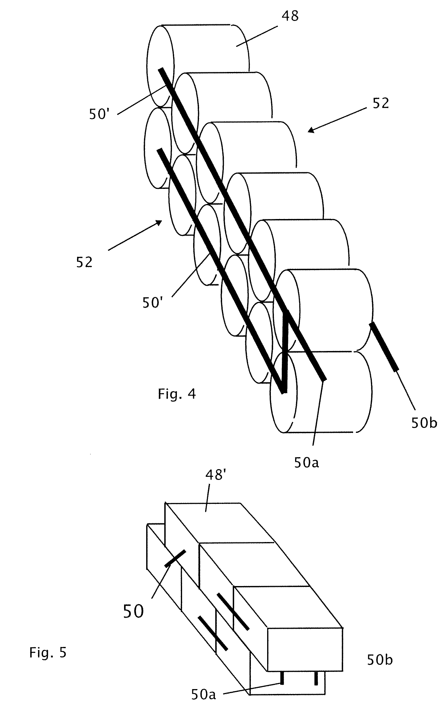
[0018]Significant improvement in energy storage system performance for electric vehicle (EV), hybrid electric vehicle (HEV) and plug-in hybrid electric vehicle (PHEV) applications can be attained by abandoning single architecture storage systems in favor of a hybrid approach. A hybrid energy storage system may be generically thought of as a system containing two or more different energy storage structures. For example, a hybrid energy storage system may incorporate two different battery chemistries and corresponding cell configurations. By optimization of the hybrid energy storage system, reductions can be obtained in the overall size, weight, cell number and control complexity with improvement in energy delivery and system life. An energy storage system with multiple modules. Modules may include set of cells having certain characteristics, such as cell configuration, cell chemistry, controls and the like. Combining modules of different types may allow improved energy delivery, over...


PUM


Abstract

A hybrid energy storage system suitable for use in a vehicle having an electrified drivetrain includes a first energy storage module and a second energy storage module that is different than the first energy storage module. The first energy storage module may have a cell configuration, a cell chemistry, a cell number, a controller or another characteristic different than a like characteristic of the second energy storage module.

Description

CROSS-REFERENCE TO RELATED APPLICATIONS[0001]This application claims priority to and benefit from U.S. Provisional Patent Application Ser. No. 60 / 909,395, filed Mar. 30, 2007, entitled Vehicle Hybrid Battery System, the disclosure of which is hereby incorporated herein by reference for all purposes.GOVERNMENT FUNDING[0002]The U.S. Government may have certain rights in this invention as provided for by the terms of Contract No. EEC 9986686 awarded by The National Science Foundation—Wireless Integrated Microsystems Engineering Research Center (NFS-WIMS ERC).TECHNICAL FIELD[0003]This patent relates to energy storage systems. More particularly, this patent relates to energy storage systems for electric and hybrid electric vehicles, and in particular, to a hybrid energy storage system suitable for use in vehicles having a total or partial electrified drivetrain and other applications, such as residential electric.BACKGROUND[0004]The design of an electrical energy storage system for an el...

Claims


Application Information

Patent Timeline
IPC IPC(8): B60K6/28B60L50/16
CPCB60K1/02B60K6/28B60K6/442B60K6/547B60W10/26B60W20/00B60W2510/244B60W2510/246B60W2520/10H01M10/052H01M10/345Y02T10/6234Y02T10/6278Y02T10/7011B60Y2400/114Y02E60/10Y02T10/62
Inventor SASTRY, ANN M.COOK-CHENNAULT, KIMBERLY A.WANG, CHIA W.ALBANO, FABIO
Owner THE RGT OF THE UNIV OF MICHIGAN
Why Eureka
Try Eureka