Polymer blend membranes for fuel cells and fuel cells comprising the same
- Summary
- Abstract
- Description
- Claims
- Application Information
AI Technical Summary
Benefits of technology
Problems solved by technology
Method used
Image
Examples
example 1
Polymer Blend Membranes Having Co-Continuous Morphology
[0049]Sulfonated poly(arylene ether sulfone) copolymer and nonsulfonated poly(ether sulfone) copolymer were blended with 1:1 weight based blend ratio in N,N-dimethylacetamide (DMAc). Initial casting concentration was from 20 wt % (Blend 1) to 15 wt % (Blend 2) and cast solution was freeze dried at −75° C. for 140 hours under vacuum condition and then the temperature was raised to 100° C. to remove the residual solvent completely.
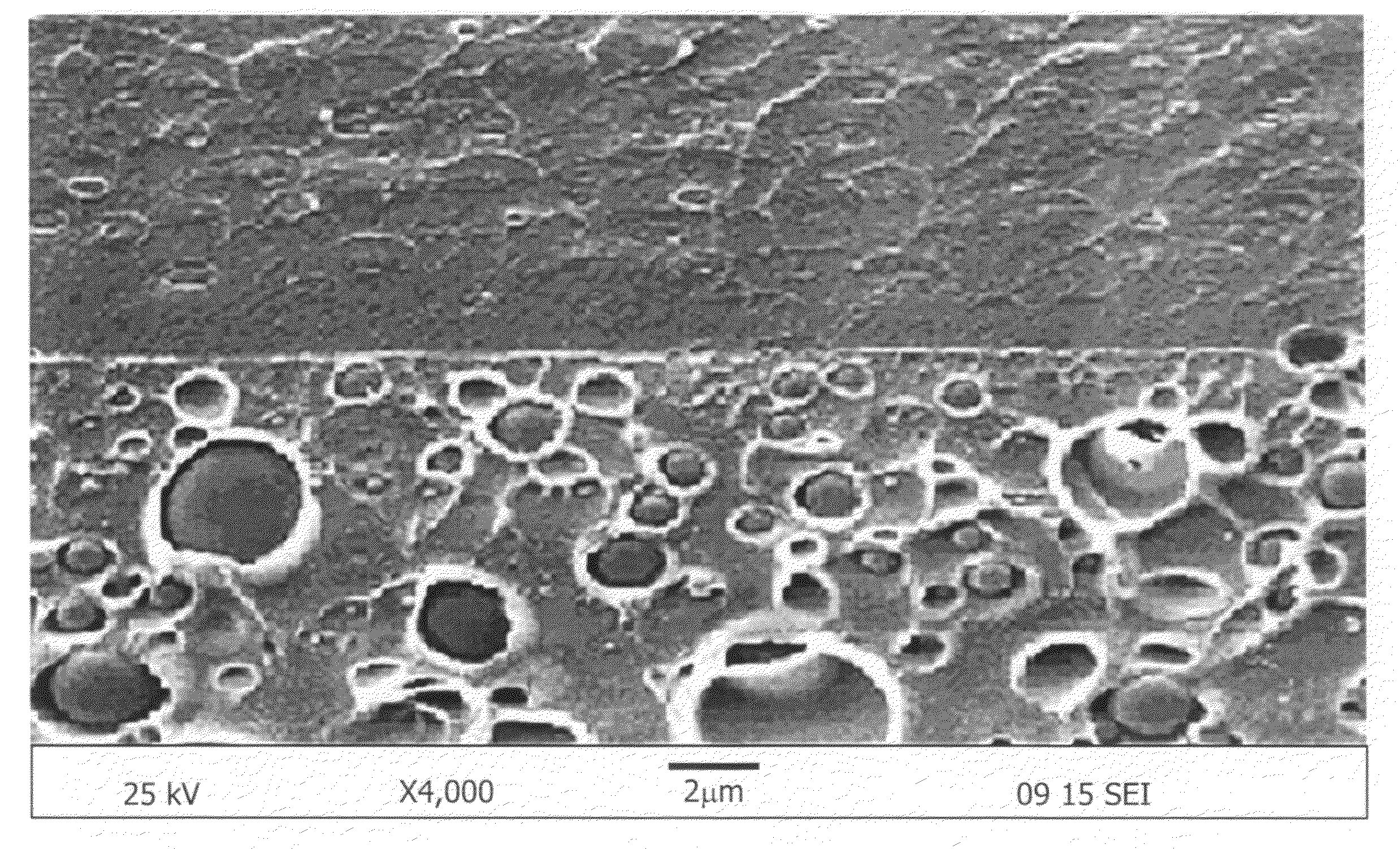
[0050]According to scanning electron microscopy, the size of the co-continuous domain was less than 1 μm.
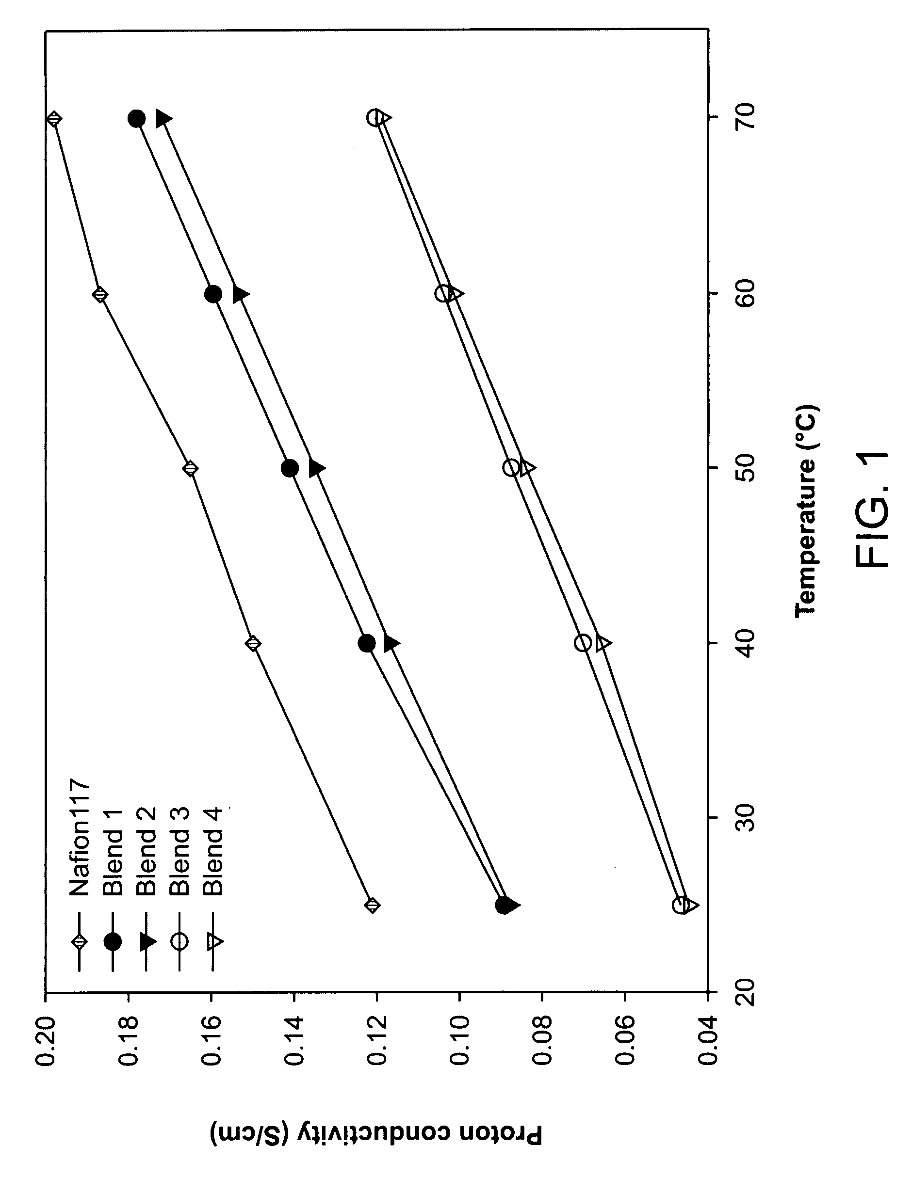
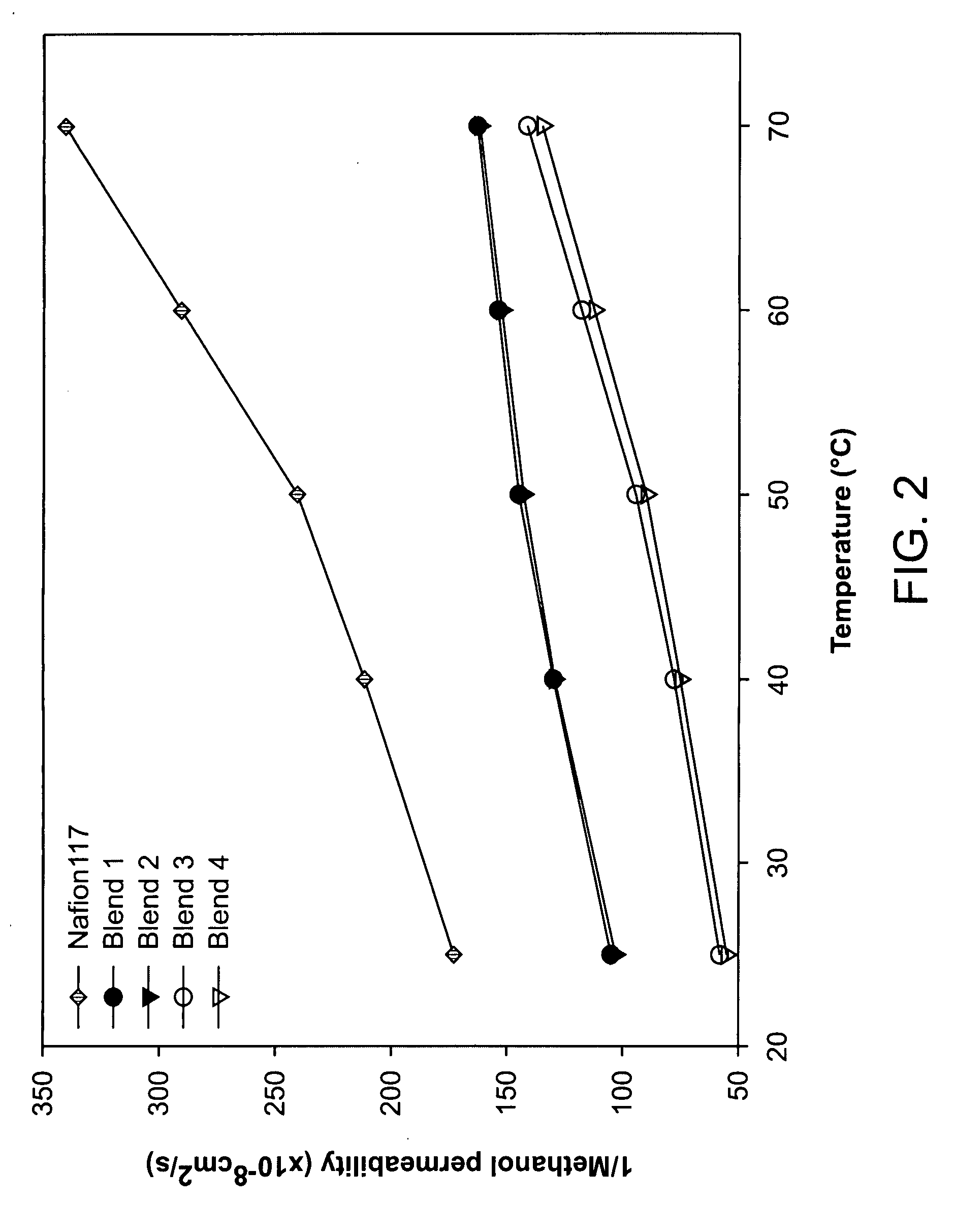
[0051]Well developed hydrophilic channels facilitated proton movement and hydrophobic network restricted the methanol crossover. Consequently, fuel leakage was effectively limited and membrane selectivity was maximized, and excellent selectivity was maintained even at a high temperature. Transport properties of the blend membranes measured at different temperature are shown in FIGS. 1-3. Proton conduc...
example 2
Polymer Blend Membranes Having Two-Layer Morphology
[0052]Sulfonated poly(arylene ether sulfone)copolymer and nonsulfonated poly(ether sulfone)copolymer were blended with 1:1 weight based blend ratio in N,N-dimethylacetamide (DMAc). Initial casting concentration was 15 wt % (Blend 3) to 10 wt % (Blend 4). Cast solution was dried at 80° C. under ambient atmosphere for 12 hours and then dried at 120° C. under vacuum for 24 hours to remove the residual solvent completely.
[0053]Two layered morphology was characterized through scanning electron microscopy and energy dispersive X-ray analysis.
[0054]Even though the proton conductivity and membrane selectivity were not higher than those of co-continuous morphology as shown in FIGS. 1 and 3, nonsulfonated poly(ether sulfone)copolymer rich layer reduced the methanol crossover remarkably as shown in FIG. 2.
example 3
Preparation of DMFC
[0055]The cathode catalyst ink was prepared by mixing 20 wt % Pt / C, 5 wt % Nafion dispersion (DuPont), and isopropanol together. The catalyst loading on the anode side was 3 mg / cm2 with PtRu black (1:1 a / o) and 5 wt % of Nafion solution. After the mixture was stirred and dispersed uniformly, catalyst ink was directly coated onto the carbon paper to form a catalyst layer. Both electrodes were dried at 70° C. for 1 hour and then the Nafion and isopropanol mixture (weight ratio was 1:3) was coated on the electrode surface. Finally, membrane electrode assembly with an active area of 3 cm2 was fabricated by hot pressing at 125° C. and 100 atm. When the polymer blend membrane with two-layer morphology was applied to DMFC application, the layer having the highly sulfonated polysulfone matrix with a high proton conductivity was faced to the cathode, and the layer having the nonsulfonated polysulfone matrix with a low methanol permeability was faced to the anode.
PUM
| Property | Measurement | Unit |
|---|---|---|
| Electrical conductivity | aaaaa | aaaaa |
| Electrical conductivity | aaaaa | aaaaa |
| Phase separation | aaaaa | aaaaa |
Abstract
Description
Claims
Application Information
 - R&D
- Intellectual Property
- Life Sciences
- Materials
- Tech Scout
- Unparalleled Data Quality
- Higher Quality Content
- 60% Fewer Hallucinations
Browse by: Latest US Patents, China's latest patents, Technical Efficacy Thesaurus, Application Domain, Technology Topic, Popular Technical Reports.
© 2025 PatSnap. All rights reserved.Legal|Privacy policy|Modern Slavery Act Transparency Statement|Sitemap|About US| Contact US: help@patsnap.com


