
Thermally assisted magnetic head, head gimbal assembly, and hard disk drive

a technology of magnetic head and head gimbal, which is applied in the direction of combination recording, data recording, instruments, etc., can solve the problems of insufficient intensity of recording magnetic field generated, fading to realize hard disk drives with high transfer rate, etc., and achieves simple structure, shortening time elapse, and increasing the effect of effective refractive index

Active Publication Date: 2008-10-02
TDK CORPARATION
View PDF9 Cites 35 Cited by
  • Summary
  • Abstract
  • Description
  • Claims
  • Application Information

AI Technical Summary

Benefits of technology

The present invention provides a thermally assisted magnetic head that can respond to high recording frequencies. The head has a structure that allows for a longer distance between the optical waveguide and the magnetic recording medium, reducing the time required for heating the medium and applying a magnetic field. The head also has a sufficient intensity of the recording magnetic field to heat the recording area of the medium. Additionally, the invention provides a composite thin-film magnetic head that can be manufactured using conventional methods. The technical effects of the invention include improved recording performance and higher recording frequency of the thermally assisted magnetic head.

Problems solved by technology

However, the thermally assisted magnetic head described in the above-mentioned Patent Document 1 is problematic in that it cannot respond to high recording frequencies, thereby fading to realize hard disk drives having a high transfer rate.
However, magnetic recording is required to be performed at about 1 ns / bit at a recording frequency of 1 GHz, for example, whereby recording systems required to keep a high-temperature of the magnetic recording medium over 35 ns as mentioned above are hard to respond to high recording frequencies.
The structure of the thermally assisted magnetic head disclosed in the above-mentioned Nonpatent Document 1 is excellent in this respect, but is problematic in that the intensity of the recording magnetic field generated is insufficient.

Method used


Image

  • Thermally assisted magnetic head, head gimbal assembly, and hard disk drive
  • Thermally assisted magnetic head, head gimbal assembly, and hard disk drive
  • Thermally assisted magnetic head, head gimbal assembly, and hard disk drive

Examples


first embodiment

[0096]To begin with, the first embodiment of the thermally assisted magnetic head, head gimbal assembly, and hard disk drive in accordance with the present invention will be explained.

Hard Disk Drive

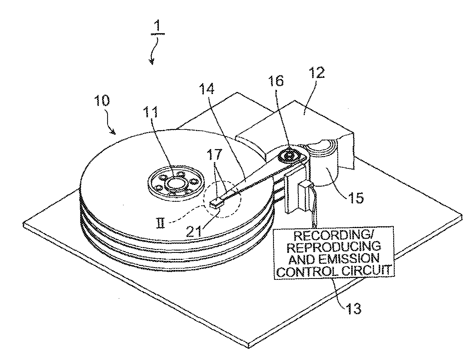
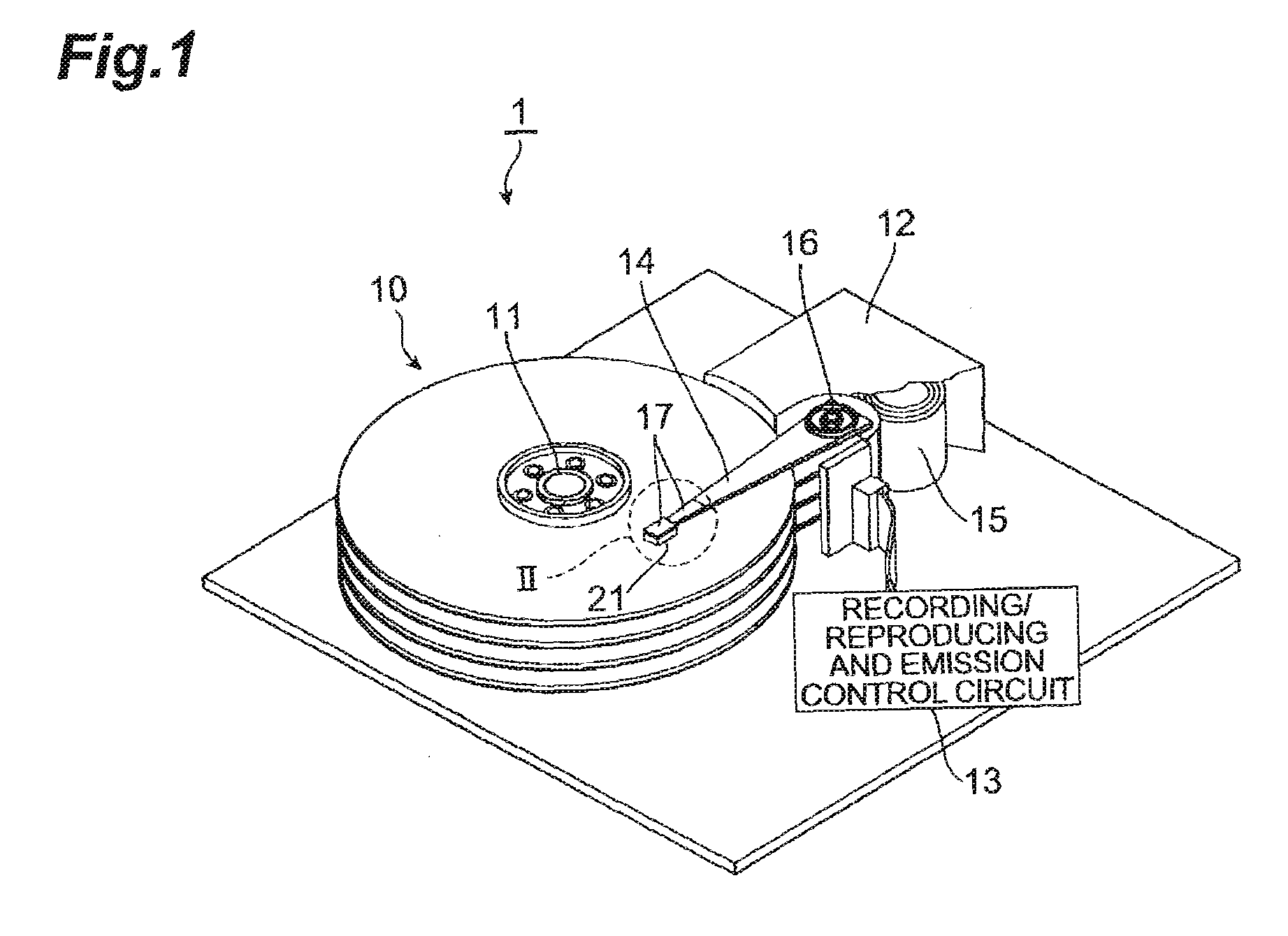
[0097]FIG. 1 is a perspective view of the hard disk drive in accordance with the embodiment.

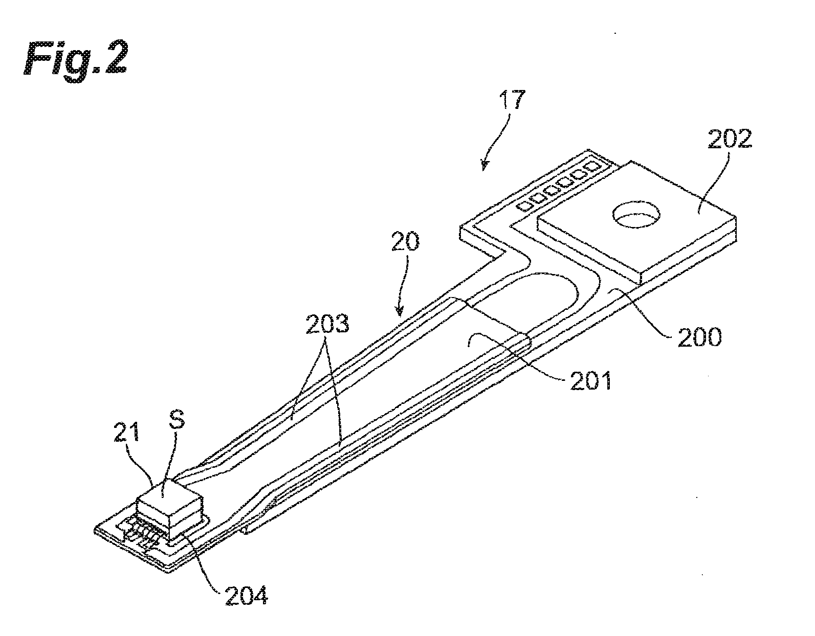
[0098]The hard disk drive I comprises magnetic disks 10 which are a plurality of magnetic recording media rotating about a rotary shaft of a spindle motor 11, an assembly carriage device 12 for positioning thermally assisted magnetic heads 21 onto tracks, and a recording / reproducing and emission control circuit (control circuit) 13 for regulating writing and reading operations of the thermally assisted magnetic heads 21 and further controlling a laser diode which is a light source for generating laser light for thermally assisted magnetic recording which will be explained later in detail.

[0099]The assembly carriage device 12 is provided with a plurality of driving arms 14. These driving arms 14 ca...

second embodiment

[0234]The second embodiment of the thermally assisted magnetic head, head gimbal assembly, and hard disk drive in accordance with the present invention will now be explained with reference to FIGS. 29 to 33. FIGS. 29 to 33 correspond to FIGS. 4, 6, 8, 9, and 13 in the first embodiment, respectively. The second embodiment differs from the first embodiment in terms of modes of the main magnetic pole 340, cores 30 and 35, and near-field light generating part 36.

[0235]As shown in FIGS. 29 and 30, the leading end 3401 of the main magnetic pole 340 and the light exit surface 353 of the core 35 are located deeper by R340 (R35) than the medium-opposing surface S as in the first embodiment. Also, as in the first embodiment, the core 30 is positioned between the light exit surface 353 of the core 35 and the medium-opposing surface S. Unlike the first embodiment, however, the main magnetic pole 340 is not in contact with the upper face 352a of the core 35, but coincides therewith in terms of t...


PUM

PropertyMeasurementUnit
thicknessaaaaaaaaaa
distanceaaaaaaaaaa
recording frequenciesaaaaaaaaaa

Abstract

The thermally assisted magnetic head comprises a medium-opposing surface; a magnetic recording device whose distance from a main magnetic pole to a medium is set longer than a distance from the medium-opposing surface to the medium; a first core for receiving light; and a second core positioned between a first light exit surface of the first core and the medium-opposing surface, having a second light exit surface on the medium side; while a distance between positions where an optical intensity distribution center within the first light exit surface and a center of the main magnetic pole are orthographically projected onto a reference plane including the second light exit surface is greater than a distance between an optical intensity distribution center within the second light exit surface and the position where the center of the leading end of the main magnetic pole is orthographically projected onto the reference plane.

Description

BACKGROUND OF THE INVENTION[0001]1. Field of the Invention[0002]The present invention relates to a thermally assisted magnetic head for writing signals by a thermally assisted magnetic recording scheme, a head gimbal assembly (HGA) equipped with the thermally assisted magnetic head, and a hard disk drive equipped with the HGA.[0003]2. Related Background Art[0004]As hard disk drives have been increasing their recording density, thin-film magnetic heads have been required to further improve their performances. As the thin-film magnetic heads, composite thin-film magnetic heads having a structure in which a magnetization detecting device such as magnetoresistive (MR) device and a magnetic recording device such as electromagnetic coil device are laminated have widely been in use. These devices read / write data signals from / onto magnetic disks which are magnetic recording media.[0005]In general, a magnetic recording medium is a sort of discontinuous body in which magnetic fine particles g...

Claims


Application Information

Patent Timeline
Patent Type & Authority Applications(United States)
IPC IPC(8): G11B5/02
CPCG11B5/02G11B5/314G11B2005/0005G11B2005/0021
Inventor SHIMAZAWA, KOJITANAKA, KOSUKEHIRABAYASHI, HIRAKU
Owner TDK CORPARATION
Learn More