Battery Pack

Inactive Publication Date: 2008-09-25
PANASONIC CORP
View PDF5 Cites 48 Cited by
  • Summary
  • Abstract
  • Description
  • Claims
  • Application Information

AI Technical Summary

Benefits of technology

[0017]With this structure, the battery pack is made compact since it only requires the end case secured to one end of the battery, and also the connection resistance is reduced because the connection path between the battery and the circuit substrate and the external connection terminal inside the end case is made shorter. Further, the battery and the end case are securely coupled together by a simple process step of engaging the tip of the screw into the end face of the battery, and therefore the battery pack achieves both high reliability and productivity. Since the end case is secured to the battery with screws, the battery pack resists a large force applied in a direction parallel to the end face of the battery (shear direction to the screw), as well as a large force that acts to separate the end case from the battery (screw pulling direction), and therefore the battery pack exhibits high attachment strength to external forces from all directions.
[0028]The external connection terminal set in the end case should preferably be of the type that establishes or shuts connection between the battery and a device to be connected by a connector on the equipment side being inserted or removed. In a portable electronic equipment or the like that has a battery accommodating space in which the battery pack is set, the external connection terminal of this type supplies power with remarkably higher stability as compared to the flat type terminal, to which the electrode terminal of the equipment is merely abutted. Thus, the external connection terminal of this type ensures highly reliable power supply even in an environment of use in which the equipment may be subjected to vibration or impact, and also is set inside the end case easily and compactly.

Problems solved by technology

In the structure shown in Prior Art Document 1, however, because there is provided a space between the case and the battery for placing the protection element and the circuit substrate, the case is large.
While there is the risk that the circuit substrate or protection element may be damaged by vibration, it is hard to retain them in position to the battery or case, and high reliability is hard to achieve.
Also, it requires a large number of assembling process steps, because of which high productivity is hard to achieve.
However, these circuit substrate and battery are then accommodated in a case to form the battery pack and therefore it is large in size.
With this structure, the number of components is fewer and the battery pack is compact, but insertion molding presents other problems such as high equipment cost and difficulties in achieving high dimensional precision and high productivity.

Method used


Image

  • Battery Pack
  • Battery Pack
  • Battery Pack

Examples


first embodiment

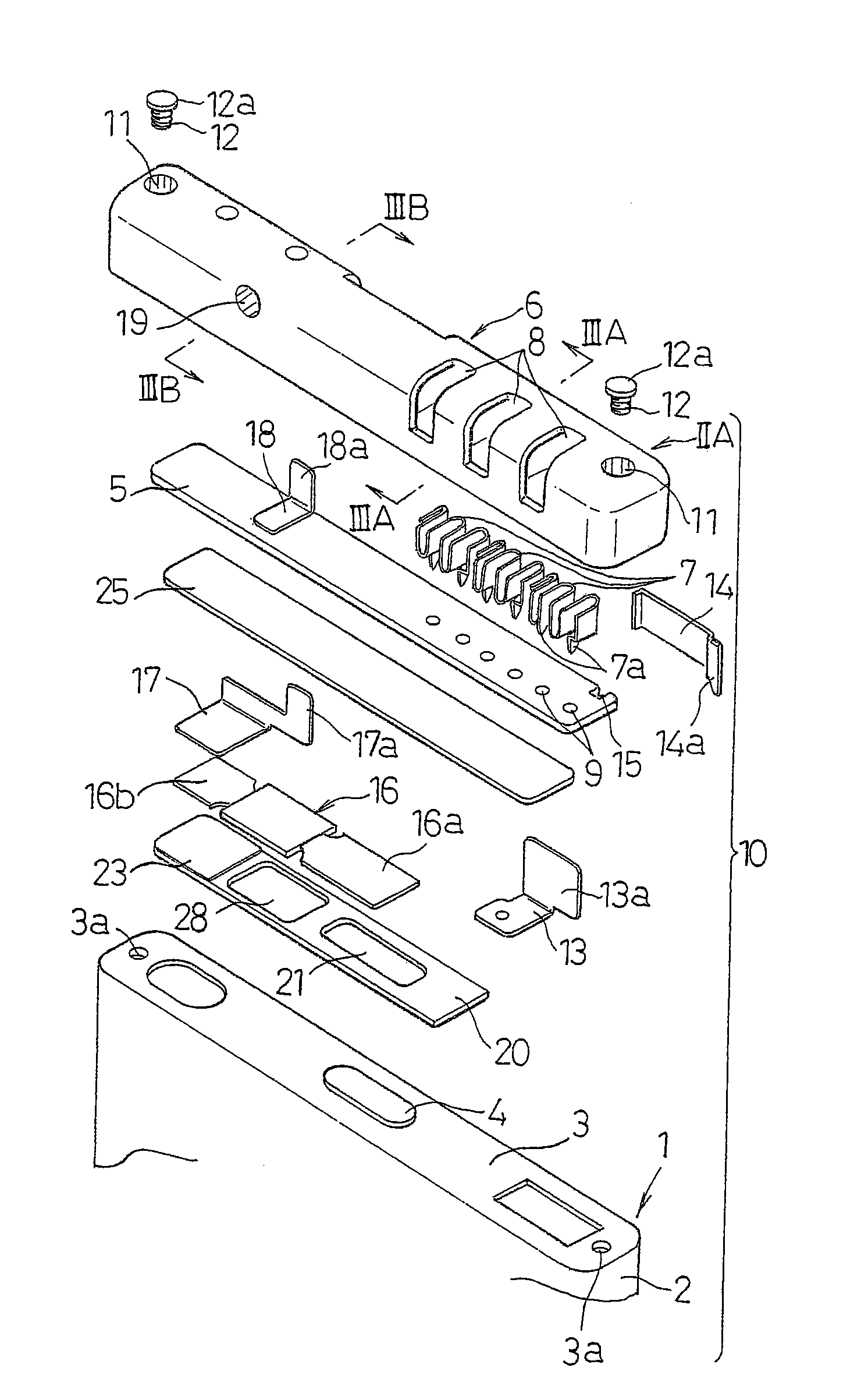
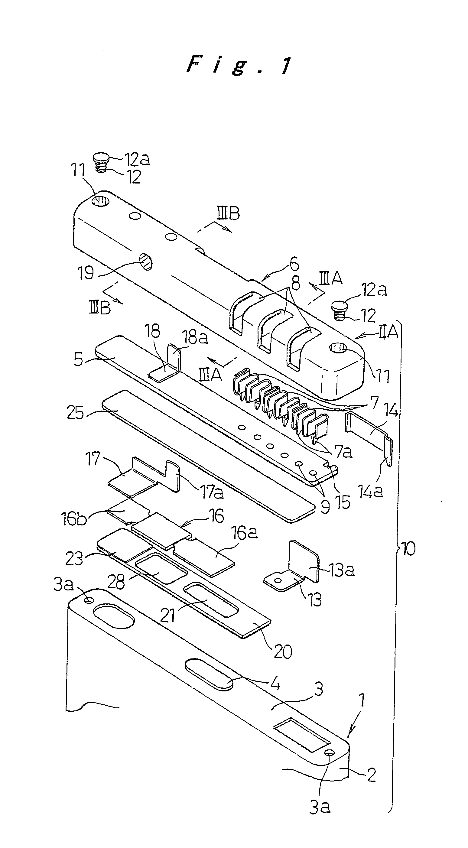
[0047]In FIG. 1, the numeral 1 denotes a prismatic battery having a flat rectangular, rounded rectangular, or oval cross section. The battery 1 is structured as a lithium ion battery, containing elements for electromotive force, i.e., an electrode plate assembly and liquid electrolyte, inside a battery case 2. The electrode plate assembly is made of strips of positive and negative electrode plates wound around with a separator interposed therebetween to have a multilayer structure. The positive electrode plate consists of a core material made of aluminum foil and positive electrode mixture paste coated and dried on the core material, the negative electrode plate consists of a core material made of copper foil and negative electrode mixture paste coated and dried on the core material, and the separator is made of a microporous polypropylene film or the like.

[0048]An electrode terminal 4 is provided to protrude in the center in one end face 3 of the battery case 2. The electrode termi...

second embodiment

[0068]A second embodiment of the invention is described next. The elements that are common to the above-described first embodiment are given the same reference numerals and will not be described again, and only the differences will be described.

[0069]In the first embodiment, the battery case 2 and the end case 6 are securely united by forcing the tips of the screws 12 into the end face 3 of the battery case 2. In this embodiment, as shown in FIG. 9 and FIG. 10, coupling pins 22 with heads 22a are set in the attachment holes 11 at both ends of the end case 6 with the heads 22a engaging with the steps 11a in the attachment holes 11, and the tips of the pins are welded to the end face 3 at both ends of the battery case 2. The welding method applicable here includes spot welding, arc welding, laser welding and others, among which spot welding is most preferable because of low cost and good working efficiency.

[0070]The difference between this embodiment and the first embodiment in the as...

third embodiment

[0073]A third embodiment of the battery pack of the invention is described next. The elements that are common to the above described first and second embodiments are given the same reference numerals and will not be described again, and only the differences will be described.

[0074]In the second embodiment, the tip of the coupling pin 22 was directly connected to the end face 3 of the battery case 2 by resistance welding. If, however, the end face 3 of the battery case 2 is made of aluminum or an aluminum alloy while the coupling pin 22 is made of an iron material such as stainless steel or nickel-plated steel so as to secure sufficient strength despite its small size, there may be cases where, by the direct resistance welding method, it is hard to achieve necessary attachment strength with high reliability. To solve this problem, in the third embodiment, the end face 3 of the battery case 2 is made of the same material as the coupling pin 22 at least in the portion to which the tip ...


PUM


Abstract

A battery pack (10) includes: a battery (1); a circuit substrate (5) having a charge / discharge safety circuit and arranged on one end face (3) of the battery; and an end case (6) in which an external connection terminal (7) is set. In this battery pack, the circuit substrate (5) is arranged inside the end case (6), and the end case (6) is secured to the battery by screws (12) with a screw head (12a) extending through and engaging with the end case (6) at both ends and tips of the screw (12) being engaged into the end face (3) at both ends of the battery (1). This achieves a compact battery pack with a reduced connection resistance, while achieving both high reliability and productivity.

Description

TECHNICAL FIELD[0001]The present invention relates to a battery pack made by coupling a battery and an end case into one piece, the end case accommodating a circuit substrate that includes a charge / discharge protection circuit and is arranged at one end of the battery.BACKGROUND ART[0002]A battery pack which is formed by uniting a circuit substrate having a charge / discharge protection circuit with a battery is required to have a compact structure, low connection resistance, high reliability of connected parts, and high production efficiency.[0003]Conventional battery packs are structured such that the battery is accommodated inside a case with a protection element and a circuit substrate. To give an example, there is known a battery pack wherein a battery is accommodated in a case having a terminal window, and a protection element and a circuit substrate are arranged in a space provided between the battery and the case. A lead plate that connects the battery with the circuit substra...

Claims


Application Information

Patent Timeline
IPC IPC(8): H01M10/40H01M50/209
CPCH01M2/1061H01M10/425H01M10/42Y02E60/10H01M50/209H01M50/20H01M10/4257H01M2200/00
Inventor OTA, SHINJISHIRASAWA, KATSUYUKIYAMASHITAFUJI, TOSHIOISHIMARU, TAKESHIMASUMOTO, KENJINIMANISHI, HIROAKI
Owner PANASONIC CORP
Why Eureka
Try Eureka