
Wireless remote-control model

Inactive Publication Date: 2008-09-11
THUNDER TIGER
View PDF7 Cites 25 Cited by
  • Summary
  • Abstract
  • Description
  • Claims
  • Application Information

AI Technical Summary

Benefits of technology

[0009]As the popularity and performance of a wireless remote-control model that uses an electric motor as its motive power source improve increasingly, the output of the electric motor becomes larger, and the energy capacity of the battery also becomes larger. In addition, more and more users or operators having little knowledge or not familiar with the wireless remote-control model, and thus it is necessary to assure the safety of the electric motor with a large output as well as the safety of the battery with a large energy capacity. If an operating control device of its control device installed on a wireless remote-control model has problems, then serious failure of the flying or driving of the wireless remote-control model may occur.
[0010]It is a primary objective of the present invention to provide a wireless remote-control model that can assure the safety of an operator (or a user) as well as the safety of the wireless remote-control model itself.
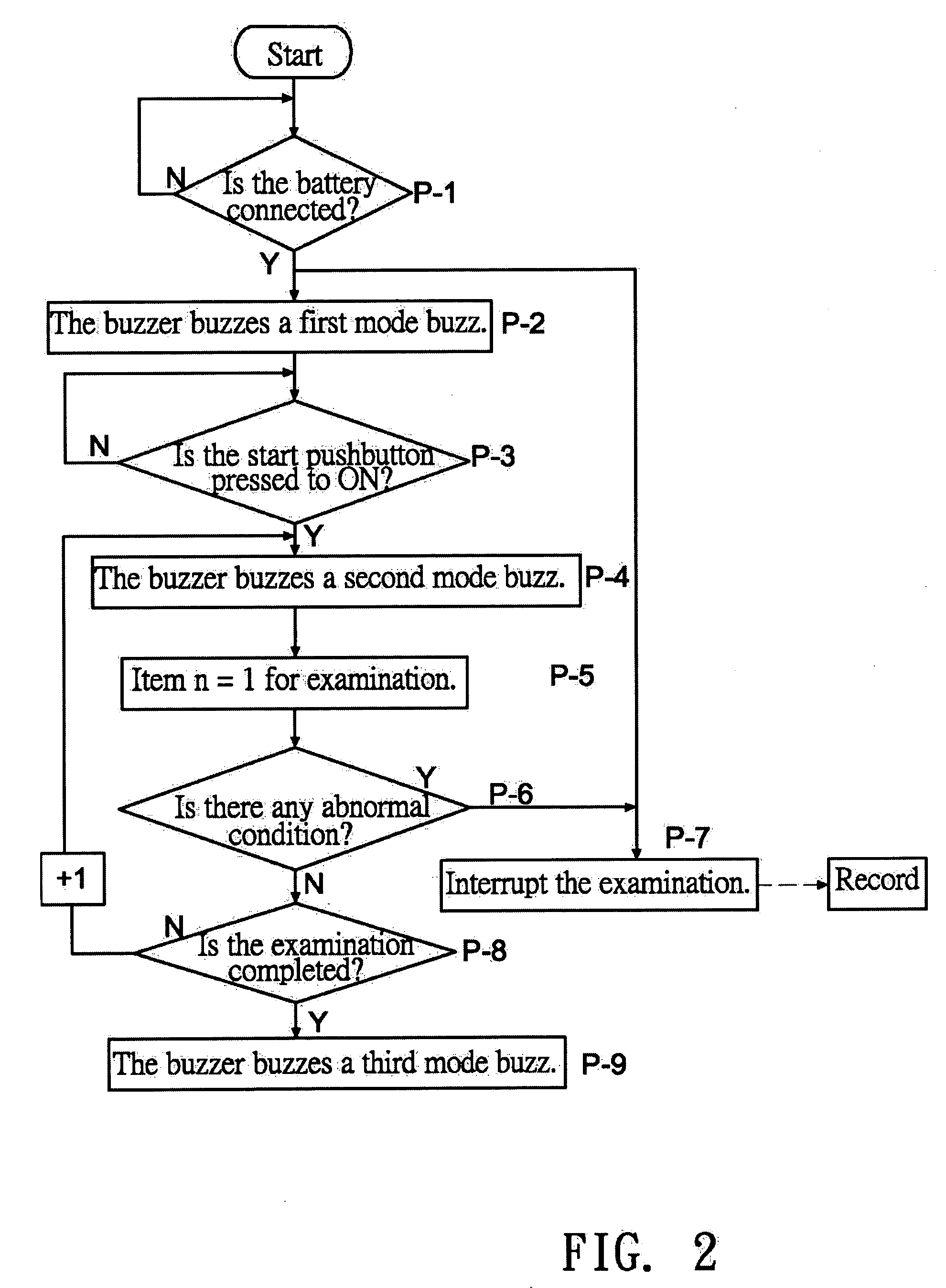
[0015]In the present invention, the first mode buzz is a heavy continuous sound, the second mode buzz is a simulated engine starter sound, and the third mode buzz is a simulated engine idling sound, so that if an internal combustion engine used for driving the wireless remote-control model has the same touch feeling, and the invention can enhance the safety even for a wireless remote-control model that adopts a silent and stable electric motor as the motive power source.
[0016]The memory has a history storage area, for recording the determination result of the safety management portion into the history storage area for making the replacement of components and the maintenance of the wireless remote-control model more easily.

Problems solved by technology

If an operating control device of its control device installed on a wireless remote-control model has problems, then serious failure of the flying or driving of the wireless remote-control model may occur.

Method used


Image

  • Wireless remote-control model
  • Wireless remote-control model
  • Wireless remote-control model

Examples


Embodiment Construction

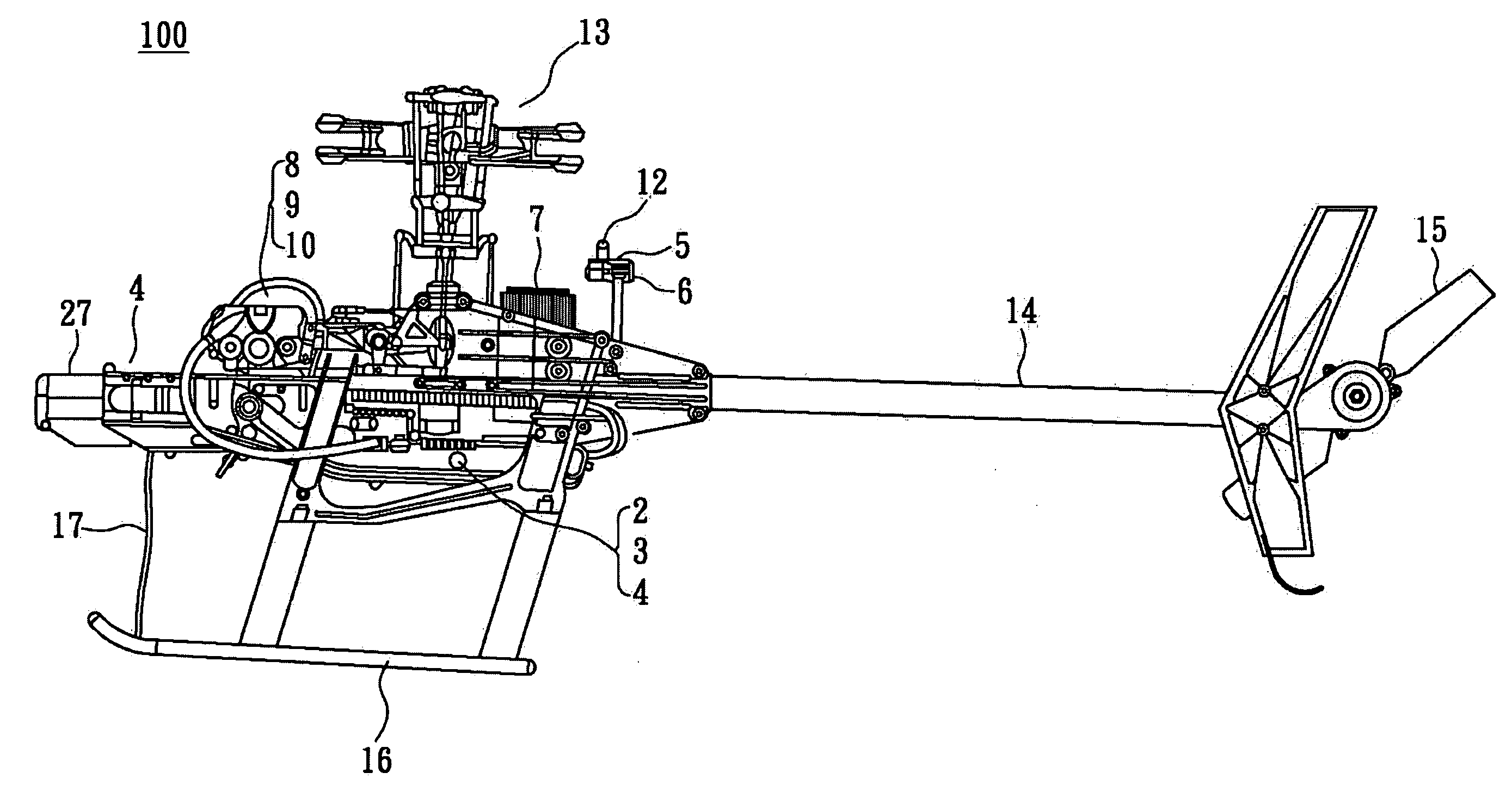
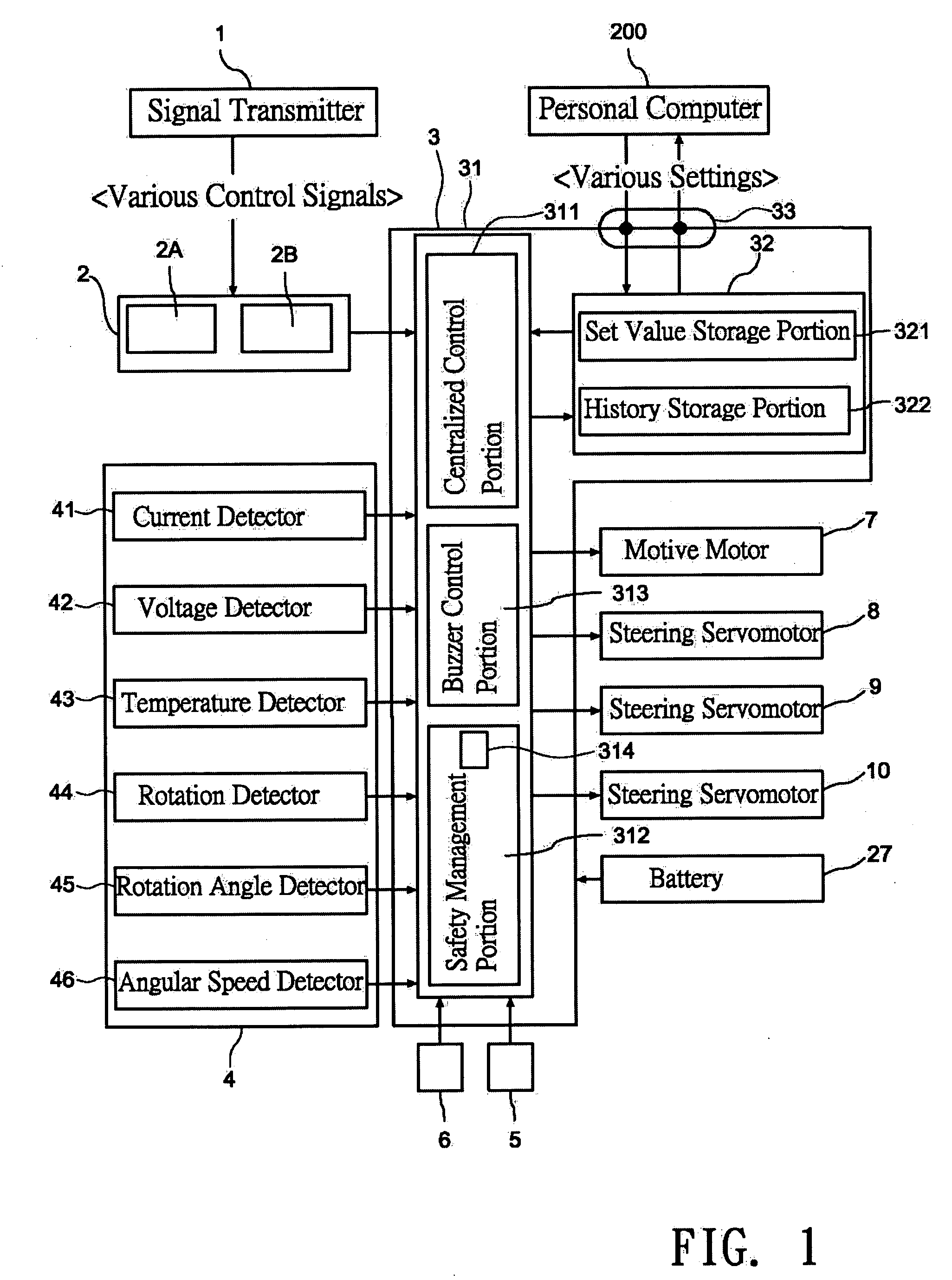
[0023]Refer to FIG. 1 for a block diagram of a control system of a wireless remote-control model in accordance with a first preferred embodiment of the present invention, the numeral 1 stands for a signal transmitter, 2 for a signal receiver, 2A for a signal receiving portion (RF amplification and wave detection), 2B for a decoder, 3 for a control module, 31 for a central control device, 311 for a centralized control portion, 312 for a safety management portion, 313 for a buzzer control portion, 314 for a determination portion, 32 for a memory, 321 for a set value storage portion, 322 for a history storage portion. The detector portion 4 includes a current detector 41, a voltage detector 42, a temperature detector 43, a rotation detector 44, a rotary angle detector 45 and an angular speed detector 46. Another appropriate detector such as acoustic radar or electric wave radar can be used as well.

[0024]Further a power motor 7 is installed at the position of a control module 3 for cont...


PUM


Abstract

A wireless remote-control model includes a safety management portion having a central control device, and the safety management portion includes a determination portion, such that when a battery is connected correctly, a first mode buzz signal instruction is sent to a buzzer control portion for indicating that the battery is connected. If the battery is connected correctly and a start pushbutton is pressed during an examination period, or a second mode buzz signal instruction is sent to the buzzer control portion for indicating that the operation is started, or a third mode buzz signal instruction is sent to the buzzer control portion for indicating that a power motor is at a driving idle state when the examination determines a normal condition, so as to assure the safety of an operator (or a user) as well as the safety of the wireless remote-control model itself.

Description

BACKGROUND OF THE INVENTION[0001]1. Field of the Invention[0002]The present invention relates to a wireless remote-control model, and more particularly to a wireless remote-control model that can assure the user safety of the wireless remote-control model employing an electric motor as a motive power source as well as the safety of the wireless remote-control model itself.[0003]2. Description of the Related Art[0004]Wireless controlled models such as remote-control helicopters or vehicles are also known as wireless models or wireless remote controls, not only applied in the area of amateur hobbies, but also used extensively in many industries. Particularly, a wireless remote-control model using electric motor for its motive power (such as an electric wireless remote-control model) generally installs a signal receiver, a servomotor, a speed controller, a gyroscope, an operation control device and a battery serving as a motive power source, used in an operating control machine and a c...

Claims


Application Information

Patent Timeline
IPC IPC(8): A63H27/127
CPCA63H30/04
Inventor TAYA, SHIGETADA
Owner THUNDER TIGER
Learn More