
Silicon Spout-Fluidized Bed

a technology of fluidized bed and silicon, which is applied in the direction of silicon compounds, coatings, chemistry apparatuses and processes, etc., can solve the problems of large energy consumption of processes, inability to meet the needs of distribution, and inherently unstabl

Inactive Publication Date: 2008-09-11
REC SILICON
View PDF23 Cites 61 Cited by
  • Summary
  • Abstract
  • Description
  • Claims
  • Application Information

AI Technical Summary

Benefits of technology

[0003]Polycrystalline silicon (polysilicon) is a critical raw material for both the semiconductor and photovoltaic industries. While there are alternatives for specific applications, polysilicon will be the preferred raw material in the foreseeable future. Hence, improving the availability of and economics for producing polysilicon will increase the growth opportunities for both industries.
[0005]Many have considered pyrolytic decomposition of silicon-bearing gas in fluidized beds an attractive alternative to produce polysilicon for the photovoltaic and semiconductor industries due to excellent mass and heat transfer, increased surface for deposition and continuous production. Compared with the Siemens-type reactor, the fluidized bed reactor offers considerably higher production rates at a fraction of the energy consumption. The fluidized bed reactor can be continuous and highly automated to significantly decrease labor costs.
[0008]Prior silicon spout nozzle designs include regions of reduced particle movement in and around the spout base. Reduced movement could allow recently formed silicon powder having non-bonded electrons to adhere to the spout chamber surface and form undesired silicon deposits. Deposits near a spout nozzle can completely engulf it and reduce silicon production efficiency and duration. Previous designs mention cooling the spout nozzle to keep the silicon-bearing gas inlet temperature below a certain temperature to prevent deposition of silicon inside the spout nozzle but do not address the fundamental issue of silicon deposition on and around the nozzle surface within the spout chamber.

Problems solved by technology

The Siemens process requires large amounts of energy per kg polysilicon produced and then substantial manual efforts to convert polysilicon rods into smaller chunks required for crystal growing.
Because there is no control of gas distribution between the orifices they are inherently unstable.
Distributor designs are prone to silicon deposition on the plate and high powder production.
However this creates create a large heat sink which significantly reduces the energy efficiency of a fluidized bed reactor.
Deposits near a spout nozzle can completely engulf it and reduce silicon production efficiency and duration.
Previous designs mention cooling the spout nozzle to keep the silicon-bearing gas inlet temperature below a certain temperature to prevent deposition of silicon inside the spout nozzle but do not address the fundamental issue of silicon deposition on and around the nozzle surface within the spout chamber.

Method used


Image

  • Silicon Spout-Fluidized Bed
  • Silicon Spout-Fluidized Bed
  • Silicon Spout-Fluidized Bed

Examples


example 1

Effect of Cooled Nozzle on Eliminating Dendrite Formation

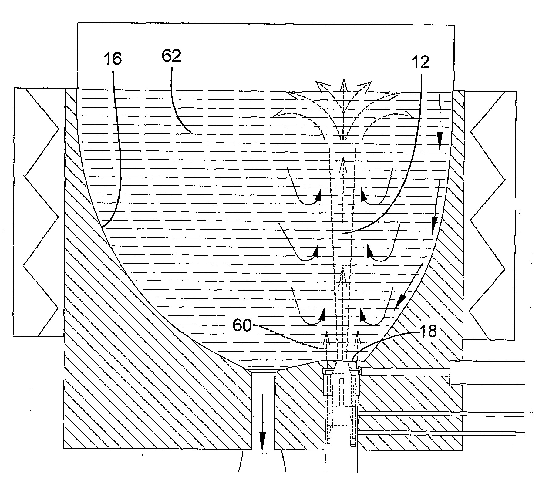
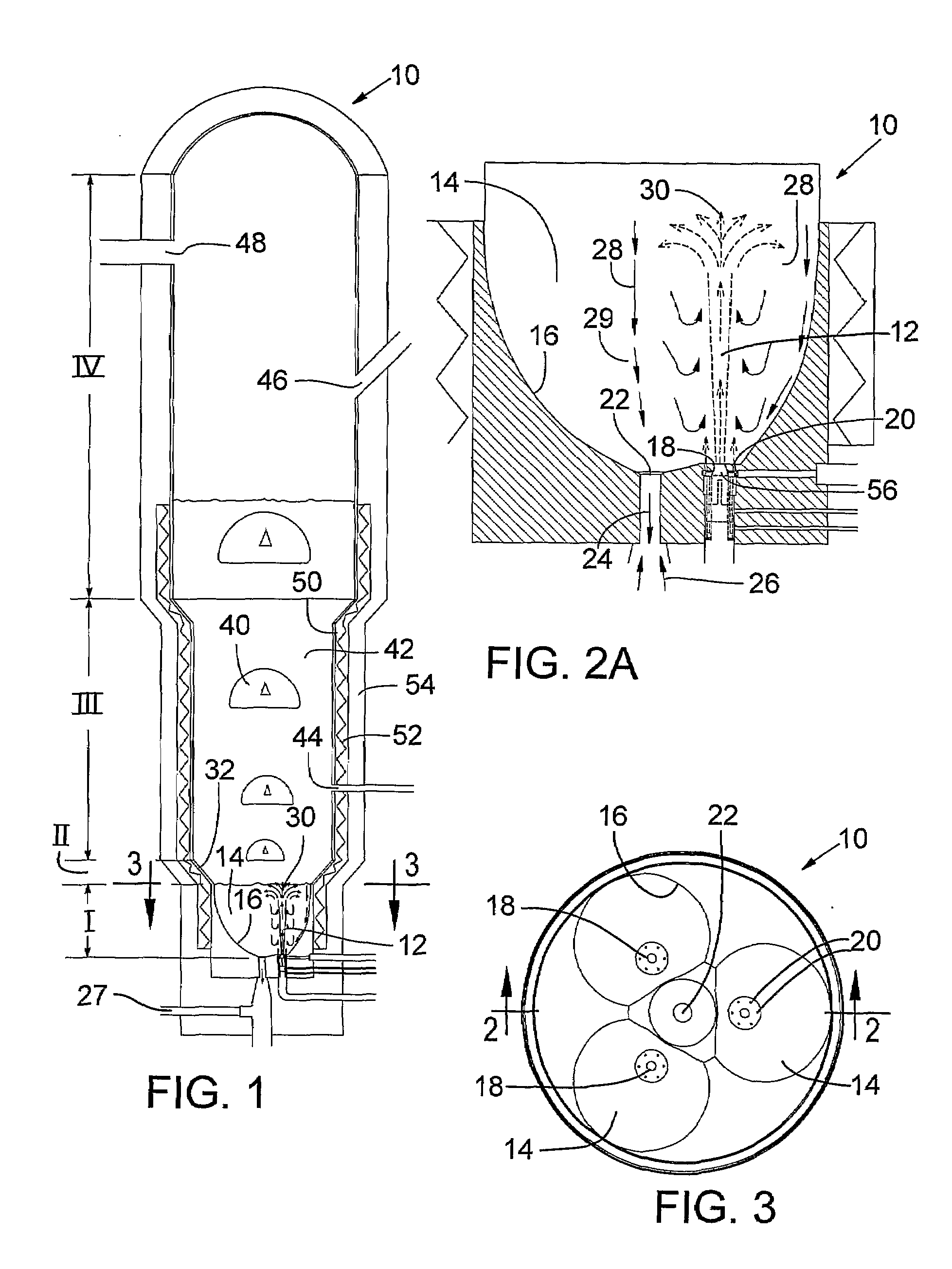
[0066]The reactor system was an open configuration system with three spouts surrounding a common central outlet as illustrated in FIGS. 1-3. Each nozzle tip was water cooled to maintain a surface temperature not much above 100° C. Each spout nozzle was fed a mix of 600 slm hydrogen and 100 slm silane preheated to 300° C. About 100 slm hydrogen preheated to 200° C. was distributed to each set of six secondary orifices around the nozzles. The pressure in the freeboard region (IV) was controlled at 0.35 barg. The walls of the spout region were about 650° C. while the wall temperatures of the fluidized bed region were well above 700° C. Measured bed temperature was about 690-700° C. After several days operation there was no sign of deposition at or near the primary nozzles.

[0067]When nozzle cooling was turned off, significant deposition would occur in only a few days at the same conditions.

example 2

Effect of Secondary Gas on Protruding Nozzles

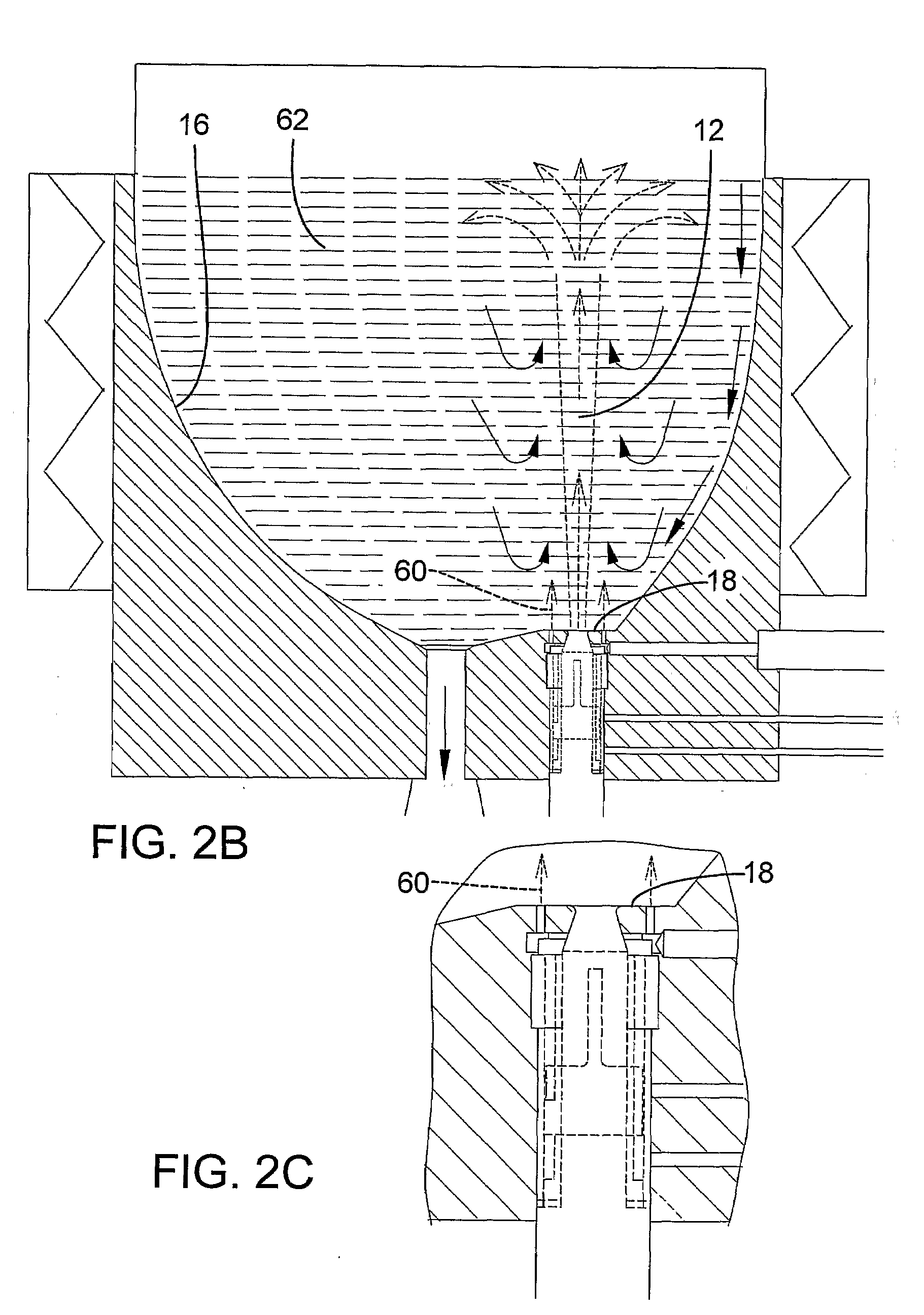
[0068]The reactor system was an open configuration as in Example 1 but with no cooling of the nozzle tips. The nozzles protruded a few inches into the spouts, as illustrated in FIG. 4B.

[0069]Each spout nozzle was fed a mix of 600 slm hydrogen and 100 slm silane preheated to 150° C. No hydrogen was distributed to the six secondary orifices surrounding each spout nozzle. The pressure in the freeboard region (IV) was controlled at 0.35 barg. The walls of the spout region (I) were heated above critical nucleation temperature but below Tamman temperature to minimize deposition while the wall temperatures of the fluidized bed region (III) are heated well above the Tamman temperature to promote scavenging and annealing of powder. Measured spout annulus temperature was 675° C., bed transition temperature was 690° C. and fluidized bed temperature was 710° C. When production was stopped after only a few days operation there was significant depositi...

example 3

Verification of Spout Penetration and Individual Spout Behavior

[0071]The reactor system was similar to Examples 1 and 2 but with a transparent plexiglas column instead of the reactor. The primary nozzle diameter was 0.375″ All flows were nitrogen at ambient temperature and pressure above bed was 0.2 atm.

[0072]The purpose of these tests was to verify spout penetration heights vs. literature correlations. The spout penetration flow was determined by increasing primary nozzle flow rate for a given particle size distribution and bed level. The flow at which spouts penetrated the bed would be the minimum flow for that spout height.

[0073]A first set of tests were with beads of average diameter 0.95 mm.[0074]1) 50 kg beads charged to the reactor yielding a stationary bed height of 45 cm.[0075]2) Total nitrogen flow to the three primary nozzles was varied between 1000 slm and 1700 slm while total nitrogen flow to secondary orifices was varied between 100 and 300 slm.[0076]3) After completin...


PUM

PropertyMeasurementUnit
angleaaaaaaaaaa
angleaaaaaaaaaa
angleaaaaaaaaaa

Abstract

Polysilicon is formed by pyrolytic decomposition of a silicon-bearing gas and deposition of silicon onto fluidized silicon particles. Multiple submerged spout fluidized bed reactors and reactors having secondary orifices are disclosed.

Description

CROSS REFERENCE TO RELATED APPLICATION[0001]This claims the benefit of U.S. Provisional Application No. 60 / 700,964, filed Jul. 19, 2005, which is incorporated herein by reference.BACKGROUND AND SUMMARY[0002]The present invention relates to pyrolytic decomposition of a silicon-bearing gas in a fluidized bed to produce polysilicon.[0003]Polycrystalline silicon (polysilicon) is a critical raw material for both the semiconductor and photovoltaic industries. While there are alternatives for specific applications, polysilicon will be the preferred raw material in the foreseeable future. Hence, improving the availability of and economics for producing polysilicon will increase the growth opportunities for both industries.[0004]The majority of polysilicon is produced by the Siemens hot-wire method with silane or trichlorosilane as the silicon-bearing gas source. The silicon-bearing gas, usually mixed in other inert or reaction gases, is pyrolytically decomposed and deposited onto a heated s...

Claims


Application Information

Patent Timeline
Patent Type & Authority Applications(United States)
IPC IPC(8): C23C16/442
CPCB01J8/1818B01J8/1827B01J8/1854B01J8/1863B01J8/245B01J8/26C01B33/027B01J2208/00407B01J2208/00415B01J2219/00038B01J2219/00119B01J2219/185B01J2219/1923B01J19/26C01B33/02B01J8/24
Inventor EGE, PAUL EDWARDHANSEN, JEFFREY A.ALLEN, LEVI C.
Owner REC SILICON
Learn More