
Receiver Circuit

a receiver circuit and circuit technology, applied in the field of receiver circuits, can solve the problems of not being able to detect the phase of a clock signal, the algorithm of bang-bang cdr is also unable to detect the phase of data, and the timing of the clock is not good for high-speed data transfer systems. achieve the effect of high clock ra

Inactive Publication Date: 2008-09-11
TEXAS INSTR INC
View PDF4 Cites 34 Cited by
  • Summary
  • Abstract
  • Description
  • Claims
  • Application Information

AI Technical Summary

Benefits of technology

[0012]By providing both baud rate and over-sampling clock recovery options, the receiver circuit of the present invention is compatible with legacy systems. The system is also extremely flexible. It should be noted that the legacy support of the over-sampling clock recovery option can only occur up to half the data rate that is available for the baud rate clock recovery option, due to the need to over-sample the data. Further, it should be noted that for some data patters, the over-sampling approach may give superior jitter tracking performance compared with some baud rate options; accordingly, an over-sampling clock recovery option may be preferable at lower data rates. The invention may provide, in a single design, clock recovery for signals compliant with lower rate standards such as XAUI (3.125 Gb / s), PCIExpress (5 Gb / s) and SR10 gen2 (5 Gb / s) using bang-bang, as well as those compliant with faster standards such as CEI 6G (11 Gb / s) and IEEE 802.3 (10.3125 Gb / s) using Mueller-Mueller.
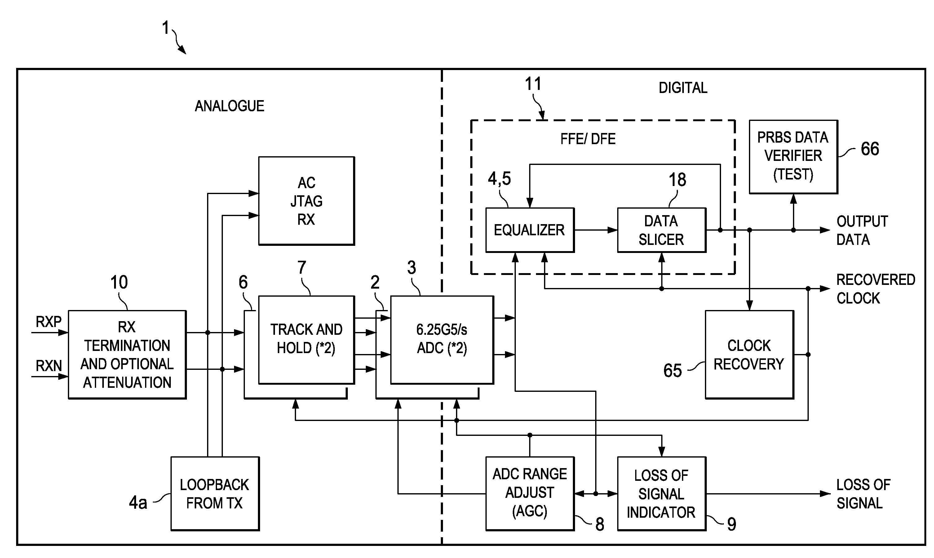
[0014]In one form of the invention, an analogue-digital converter is provided having an input coupled to said data input terminal and an output coupled to inputs of said over-sampling clock recovery system and said baud rate clock recovery system. By way of example, the analogue-digital converter may comprise two full-flash analogue-digital converters adapted to sample and convert alternate bits of the data received at said data input terminal. The use of two analogue-digital converters in this manner enables data to be sampled at a very high clock rate. The analogue-digital converter may have a sampling point that is set by said clock output; for example, said clock output may be coupled to a clock input of said analogue-digital converter.

Problems solved by technology

Bang-bang CDR and other over-sampling CDR methods are not well suited for use in high-speed data transfer systems such as the SerDes system described herein due to the sampling requirements of such over-sampling methods.
A problem with Mueller-Mueller CDR is that it is not able to detect the phase of a clock signal from an incoming data stream if that data is unchanging (i.e. 000 . . . 000 or 111 . . . 111) or if the incoming data is a clock, or clock-like signal (i.e. 10101010).
It should be noted that bang-bang CDR algorithms also have problems in detecting the phase of data that is unchanging.
As outlined above, over-sampling CDR methods, such as bang-bang CDR, are unsuitable for sampling data streams having a very high data rate.

Method used


Image

  • Receiver Circuit
  • Receiver Circuit
  • Receiver Circuit

Examples


Embodiment Construction

[0031]A key challenge facing designers of high-bandwidth systems such as data-routers and super-computers is the requirement to transfer large amounts of data between ICs—either on the same circuit board or between boards. This data transmission application is called Serialisation-Deserialisation or “SerDes” for short. The present invention is useful in SerDes circuit and indeed was developed for that application. Nonetheless the invention may be used in other applications.

[0032]Analysis of typical backplane channel attenuation (which is around −24 dB) and package losses (−1 to −2 dB) in the presence of crosstalk predict that an un-equalized transceiver provides inadequate performance and that decision feedback equalization (DFE) is needed to achieve error rates of less than 10−17.

[0033]Traditional decision-feedback equalization (DFE) methods for SerDes receivers rely on either modifying, in analogue, the input signal based on the data history [“A 6.25 Gb / s Binary Adaptive DFE with ...


PUM


Abstract

A thermometer code to sign and magnitude converter that is particularly useful in a flash ADC is provided. This comprises two conversion units. The first is a thermometer code to Gray code converter and the second a Gray code to sign and magnitude converter. Preferably, the Gray code is of a kind that has a sign bit and has the other bits symmetrically disposed about zero. This form is easily converted to a sign and magnitude code, which is advantageous as it reduces the latency of the converter, which is particularly useful at high data rates.

Description

[0001]This application claims priority under 35 U.S.C. 119(e)(1) to U.S. Provisional Application No. 60 / 889,106 (TI-63554PS) filed Feb. 9, 2007.BACKGROUND OF THE INVENTION[0002]The invention relates to a receiver circuit, in particular a receiver circuit used in high speed data transfer applications.[0003]High speed serial data transmission systems often transmit data without an accompanying clock signal. The data is input into a clock and data recovery (CDR) circuit which is used to extract a clock signal from the data. Often the approximate frequency of the required clock signal is known, but the phase is unknown. In such circumstances, a PLL at the receiver can be used, with the output of the CDR circuit being used to set the phase of the clock signal.[0004]A variety of schemes have been devised for extracting clock information from an incoming serial data stream. Two known methods are bang-bang CDR and Mueller-Mueller CDR.[0005]Bang-bang CDR is an example of an over-sampling CDR...

Claims


Application Information

Patent Timeline
IPC IPC(8): H04L7/00
CPCH04L7/033H04L7/0062G06F13/1689
Inventor SIMPSON, RICHARD D.HARWOOD, MICHAEL S.BOSSHART, PATRICK W.
Owner TEXAS INSTR INC
Learn More