Eureka AIR delivers breakthrough ideas for toughest innovation challenges, trusted by R&D personnel around the world.

Switching arrangement and DAC mismatch shaper using the same

a technology of switching arrangement and shaper, applied in the field of data conversion, can solve the problems of static mismatch errors, dynamic timing errors, limited linearity and resolution of multi-bit dacs, etc., and achieve the effect of higher clock ra

Active Publication Date: 2005-08-04
HRL LAB
View PDF34 Cites 20 Cited by
  • Summary
  • Abstract
  • Description
  • Claims
  • Application Information

AI Technical Summary

Benefits of technology

The present patent provides a switching arrangement and circuits for a mismatch shaper. The switching arrangement includes a digital input and a digital output, and a switching element that can switch between the two inputs based on a control element. The circuits include a delta-sigma modulator that can compute its output over one or more clock delays, allowing for higher clock rates. The technical effects of the patent include improved performance and reliability of the mismatch shaper, as well as increased flexibility and adaptability for different applications.

Problems solved by technology

Multibit DACs, however, have limited linearity and resolution due to mismatch errors.
Static mismatch errors occur when each DAC is driven by slightly different current sources, and dynamic timing errors occur when either the routing is unequal, or if the individual elements operate at different speeds.
The calibration method in the above Schofield paper cannot be applied to bipolar implementations because the charge cannot be easily stored on the base of the transistor.
Furthermore, calibration techniques only correct static mismatch errors, and hence some type of dynamic routing is necessary to correct timing errors.
However, mismatch-shaping circuitry to date has been too slow to linearize direct-IF generating DACs.
Bandpass mismatch shapers, which can theoretically be used to help directly generate signals closer to the Nyquist rate, have considerably higher system complexity and resultantly higher critical path delays.
Furthermore, none of these mismatch shapers have been tunable, and hence may not offer the needed flexibility for software-defined radio.

Method used


Image

  • Switching arrangement and DAC mismatch shaper using the same
  • Switching arrangement and DAC mismatch shaper using the same
  • Switching arrangement and DAC mismatch shaper using the same

Examples


Embodiment Construction

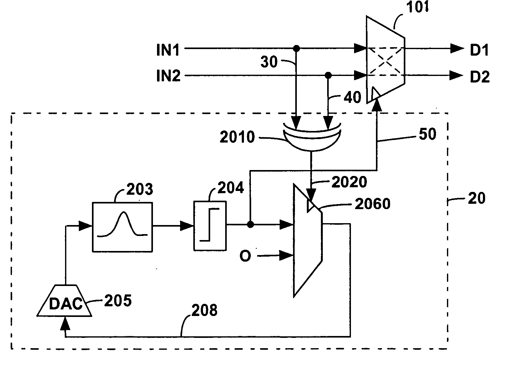
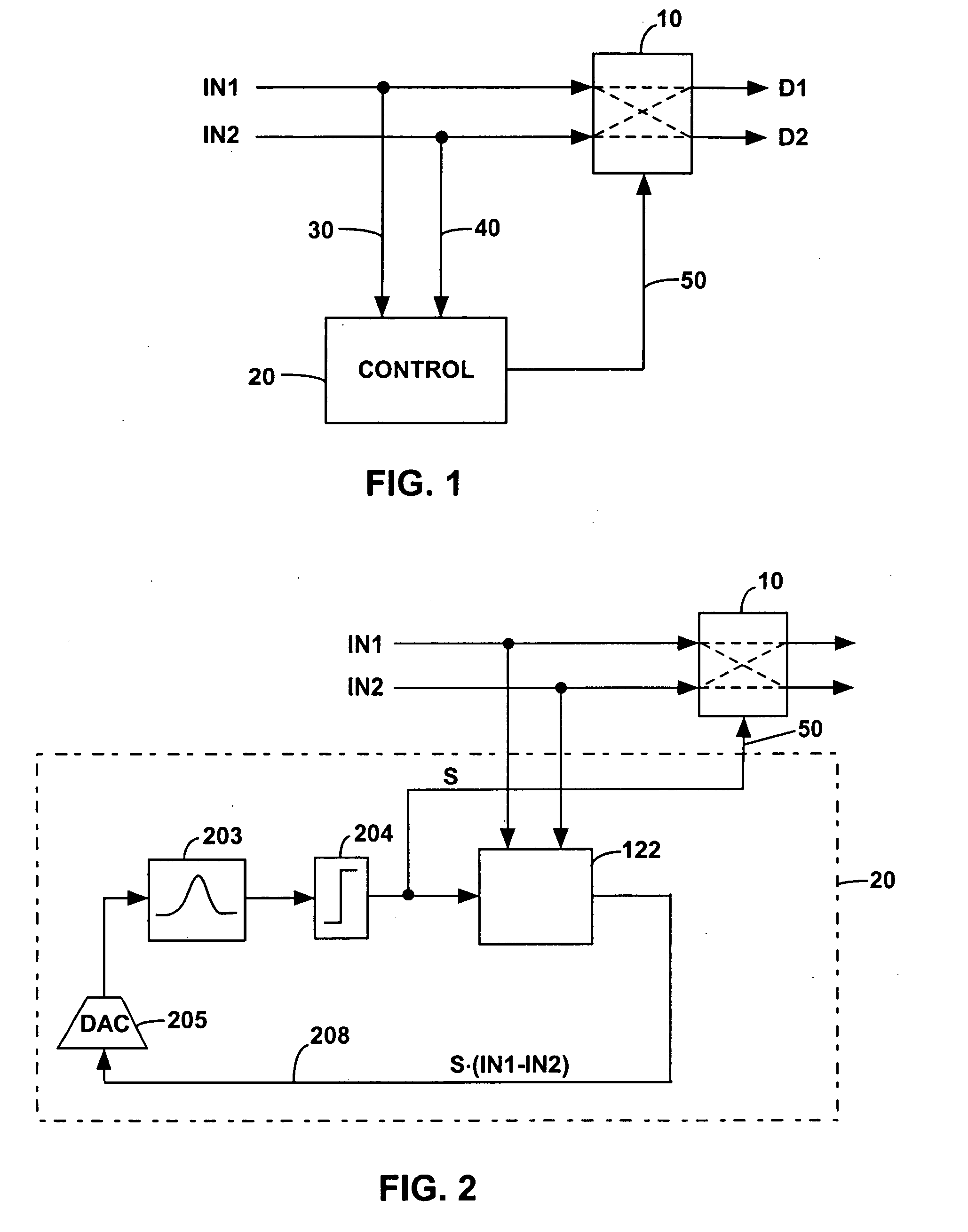
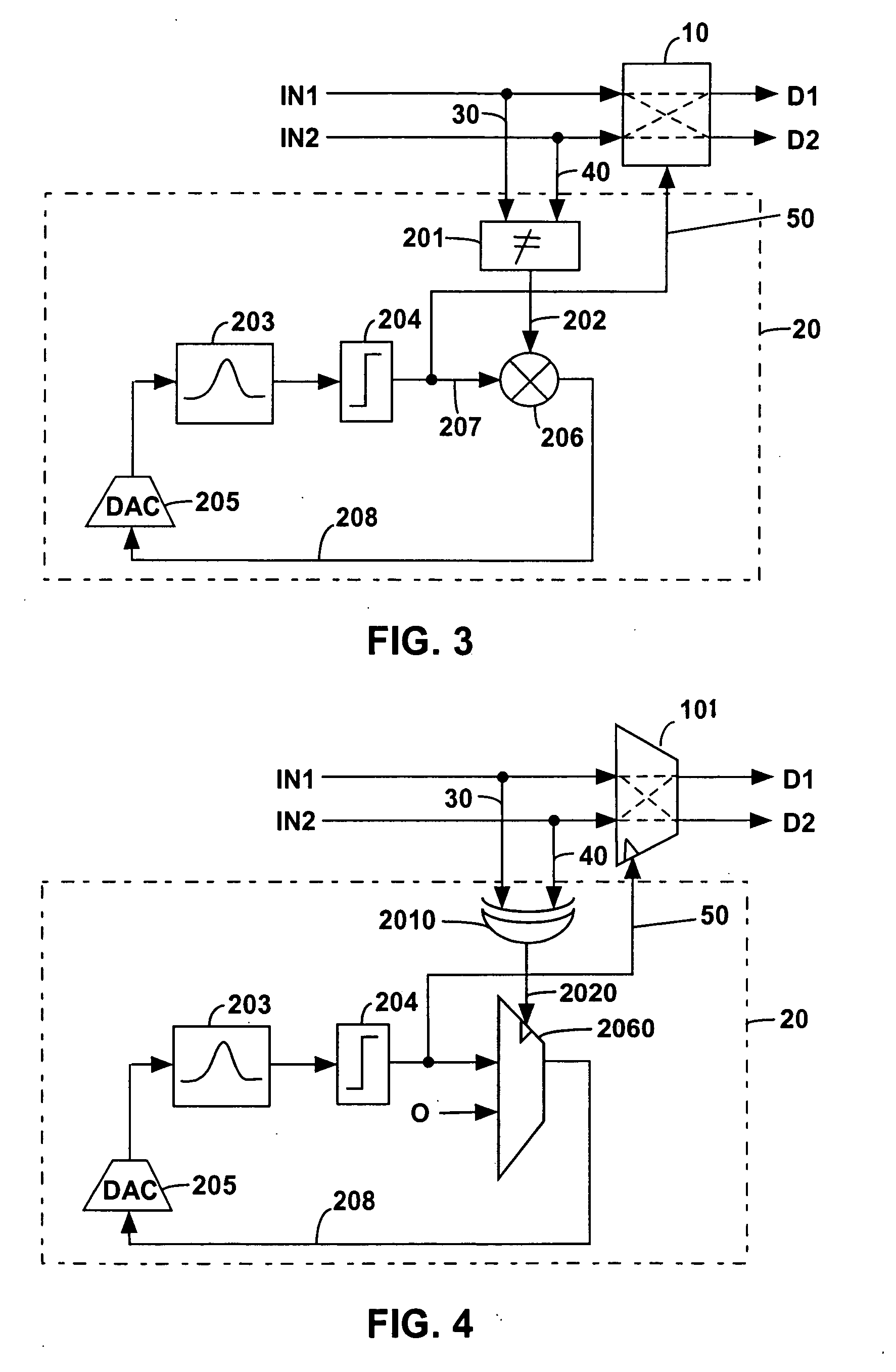
[0048]FIG. 1 shows a switching arrangement according to the present disclosure. The arrangement comprises a first digital input IN1, a second digital input IN2, a first digital output D1, and a second digital output D2. IN1 and IN2 can be n-bit digital signals, and can be originated from a 2n-bit digital signal. A switching element 10 is located between the inputs and the outputs. The switching element 10 has a first, non-switching, condition where the inputs IN1, IN2 are not switched, so that the first digital output D1 corresponds to the first digital input IN1 and the second digital output D2 corresponds to the second digital input IN2. The switching element 10 also has a second, switching, condition where the inputs IN1, IN2 are switched, so that the first digital output D1 corresponds to the second digital input IN2 and the second digital output D2 corresponds to the first digital input IN1.

[0049] Switching is controlled by a control arrangement 20, which allows the switching ...


PUM


Abstract

A digital-to-analog converter (DAC) error mismatch shaper. The shaper comprises a switching arrangement with a delta-sigma modulator having analog signal processing components. The analog signal processing components allow the spectral behavior of the shaper to be controlled. The switching arrangement comprises a control circuit. The control circuit is a tunable, pipelined control circuit.

Description

CLAIM OF BENEFIT OF PROVISIONAL APPLICATION [0001] This application claims the benefit of U.S. provisional application No. 60 / 540,909, “Switching Arrangement and DAC Mismatch Shaper Using the Same,” filed on Jan. 30, 2004, which is incorporated herein by reference in its entirety.BACKGROUND [0002] 1. Field [0003] The present disclosure relates to data conversion. In particular, it relates to a switching arrangement and to a digital-to-analog converter (DAC) mismatch shaper using the same. [0004] 2. Related Art [0005] Direct data conversion at IF frequencies offers many advantages in transceiver design. By eliminating the IF mixers and filters, the resultant system is smaller and simpler than a traditional IF transceiver architecture. Additionally, by eliminating the 1st-IF upconversion, direct-IF data conversion avoids the noise, linearity, I / Q cancellation and clock feedthrough issues that plague mixer designs. Finally, the flexibility inherent in direct IF data conversion helps en...

Claims


Application Information

Patent Timeline
Patent Type & Authority Applications(United States)
IPC IPC(8): H03M1/06H03M1/66H03M1/74H03M3/00H03M3/04
CPCH03M1/0665H03M3/464H03M1/74
Inventor KAPLAN, TODD
Owner HRL LAB
Why Eureka
Eureka Blog
Learn More