
Gas heating apparatus and methods

a heating apparatus and gas technology, applied in the direction of electric heating fuel, domestic heating details, drying chambers/containers, etc., can solve the problems of safety risk, inefficiency of conventional wire-based electric heating elements in heating gas, etc., and achieve the effect of boosting the resistivity of the thermally sprayed heater layer

Inactive Publication Date: 2008-09-11
REGAL WARE
View PDF38 Cites 24 Cited by
  • Summary
  • Abstract
  • Description
  • Claims
  • Application Information

AI Technical Summary

Benefits of technology

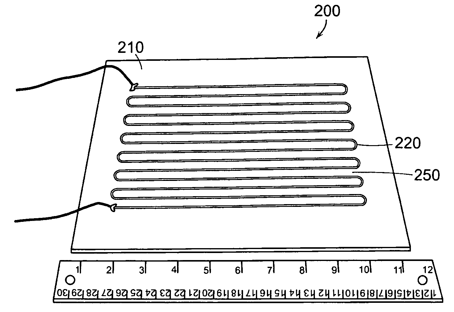
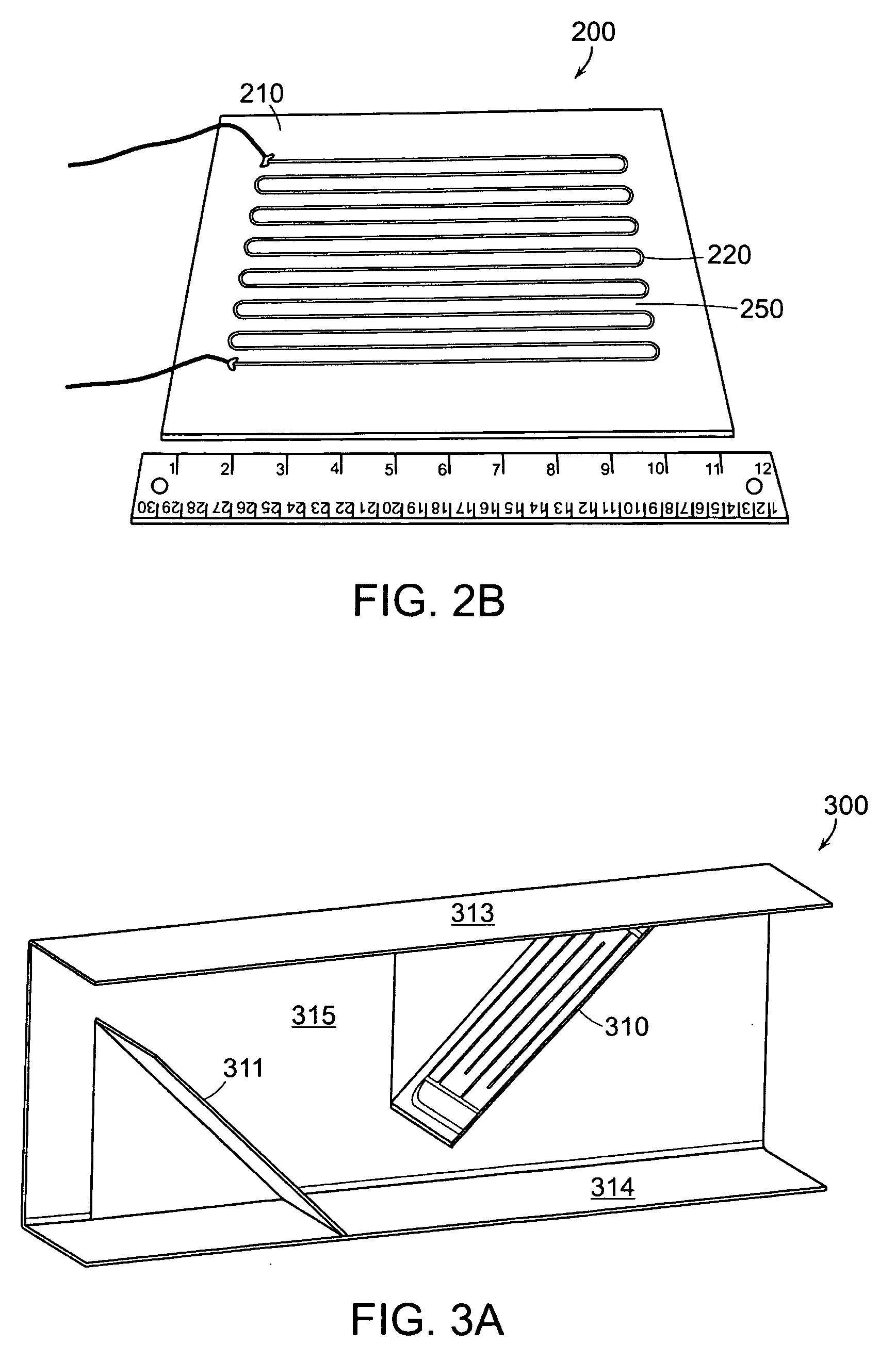
[0010]In certain embodiments, the present gas heaters distribute their power over a much larger area than a conventional heater with a wire heating element, thus the present heaters typically run cooler than wire heaters operating at the same power. Furthermore, the heater coatings of the invention can be bonded to the surface they cover, so that their power is transmitted to the heat transfer surface with less impedance to heat flow. The heater coatings of the invention can also be made very thin—typically 0.030 inches or less—resulting in a very compact gas heating apparatus, particularly in relation to bulky wire-wound heaters. The present apparatus can also be less expensive to manufacture than wire heaters because wire heaters often have complicated assembly issues and / or require expensive specialized assembly machinery.
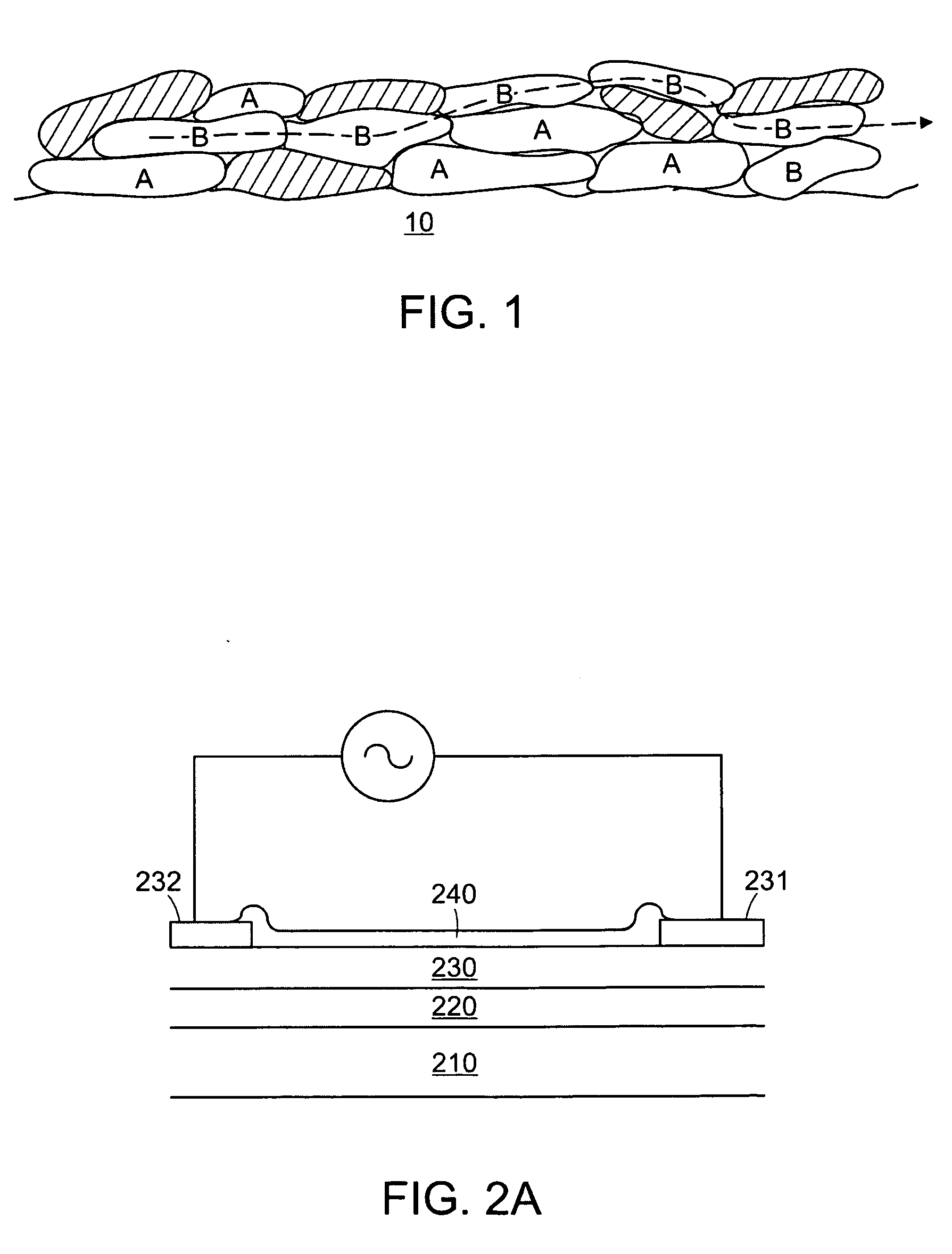
[0015]According to yet another aspect of the invention, a method for thermally spraying a heater onto a substrate comprises providing a metallic material having a core and an insulator within the core, and thermally spraying the metallic material and the insulator onto a substrate to form a heater. The metallic material and the insulator can be thermally sprayed in the presence of a reaction gas that reacts with the metallic material to produce an insulating reaction product. This can further boost the resistivity of the thermally sprayed heater layer.

Problems solved by technology

The conventional wire-based electric heating elements are therefore not very efficient in heating gas, due to this radiant heat loss.
Furthermore, the intense radiant heat generated by the wire heating element can heat up surrounding structures to dangerous temperatures, which can pose a safety risk.
For example, in the case of a clothes dryer, the radiant heat from the heating element can heat components of the dryer that are accessible to users, which can result in burns.

Method used


Image

  • Gas heating apparatus and methods
  • Gas heating apparatus and methods
  • Gas heating apparatus and methods

Examples


Embodiment Construction

[0030]Resistive heating elements can be formed by a thermal spray process. Thermal spray is a versatile technology for depositing coatings of various materials, including metals and ceramics. It includes systems that use powder as feedstock (e.g., arc plasma, flame spray, and high velocity oxy-fuel (HVOF) systems), systems that use wire as feedstock (e.g., arc wire, HVOF wire, and flame spray systems), and systems using combinations of the same.

[0031]Arc plasma spraying is a method for depositing materials on various substrates. A DC electric arc creates an ionized gas (a plasma) that is used to spray molten powdered materials in a manner similar to spraying paint.

[0032]Arc wire spray systems function by melting the tips of two wires (e.g., zinc, copper, aluminum, or other metal) and transporting the resulting molten droplets by means of a carrier gas (e.g., compressed air) to the surface to be coated. The wire feedstock is melted by an electric arc generated by a potential differen...


PUM

PropertyMeasurementUnit
Reynolds numberaaaaaaaaaa
thicknessaaaaaaaaaa

Abstract

A thermally sprayed gas heater comprises a gas flow apparatus that propels a gas through a housing; and a thermally sprayed heater bonded to a surface of the apparatus, the heater positioned to heat the gas flow in the housing. In other aspects, a heater system for a turbulent flow gas duct comprises a duct having a gas flow channel, the channel having a shaped surface providing turbulent gas flow in the channel, and a thermally sprayed heater positioned to heat the gas flow in the channel.

Description

CROSS REFERENCE TO RELATED APPLICATIONS[0001]This application claims the benefit of U.S. Provisional Application No. (to be provided), filed Feb. 20, 2007 and entitled GAS HEATING APPARATUS (Express Mail Label No. 797759189), and also claims the benefit of U.S. Provisional Application No. 60 / 993,262, filed Sep. 11, 2007 and entitled THERMAL RESISTIVE HEATER. The entire teachings of the above applications are incorporated herein by reference.BACKGROUND OF THE INVENTION[0002]Various devices are known for heating a gas, such as air, and gas heating devices have been employed for numerous industrial and domestic applications, such as cooking and room heating, and in many appliances such as hair dryers and clothes dryers. In an electrical gas heater, an electric heating element is energized and gas is caused to flow past the element. The air may flow past the element either naturally or by being forced by a blower or fan.[0003]The most common electric heating element used today is a resi...

Claims


Application Information

Patent Timeline
Patent Type & Authority Applications(United States)
IPC IPC(8): H05B3/02F24H3/02F24C15/32B28D1/32B05D5/12H01C17/06F26B25/06
CPCC23C4/06Y10T29/49099F24C7/04F24D19/04F24H3/0405Y02T50/67H05B3/10F24C15/325F24H3/0411H05B1/00H05B2203/013C23C24/04Y10T156/10H05B3/16H05B2203/006D06F58/26Y02T50/60
Inventor ABBOTT, RICHARD C.
Owner REGAL WARE
Learn More