
Engine block for use in a fuel cell system

a fuel cell and engine block technology, applied in the direction of cell components, sustainable manufacturing/processing, physical/chemical process catalysts, etc., can solve the problems of large volume of packaging, large and expensive production system, and limited application of fuel cell technology

Inactive Publication Date: 2008-09-04
ULTRACELL ACQUISITION
View PDF13 Cites 35 Cited by
  • Summary
  • Abstract
  • Description
  • Claims
  • Application Information

AI Technical Summary

Benefits of technology

The present patent relates to an engine block used in a fuel cell system to convert hydrogen to electrical energy. The engine block has a fuel processor and a fuel cell stack in fluid communication via an interconnect, which simplifies the assembly and testing of the fuel cell system. The interconnect has a plurality of conduits to receive a gas flow, and the fuel cell stack and fuel processor operate at the same temperature. The engine block also has a single plate with fluid passageways formed in the top and bottom surfaces, and a plurality of ports aligned with the fluid passageways. The method for manufacturing the engine block involves forming an interconnect with a plurality of conduits, attaching a fuel processor and a fuel cell stack to the interconnect, and creating a plurality of fluid passageways. The technical effects of this invention include reducing the size and complexity of the fuel cell system, simplifying the assembly and testing of the fuel cell system, and increasing the flexibility to select the optimal balance of plant components for the specific end user.

Problems solved by technology

Fuel cell development so far has only serviced large-scale applications such as industrial size generators for electrical power back up.
While each individual component is relatively easy to assemble and test, assembling and testing a complete fuel cell system requires an excessive amount of bulky packaging and manual labor, resulting in a large and expensive to produce system.
Additionally, the fuel cell system balance of plant components are often a cost or reliability barrier, and hence must be selected based on the end user of the fuel cell system.
These joints are susceptible to degradation, relaxation, or creep at high temperatures in a short amount of time which may result in leaks and degradation.
Additionally, these joints result in added materials and assembly of the fuel cell system is not conducive to high volume manufacturing or automation.

Method used


Image

  • Engine block for use in a fuel cell system
  • Engine block for use in a fuel cell system
  • Engine block for use in a fuel cell system

Examples


Embodiment Construction

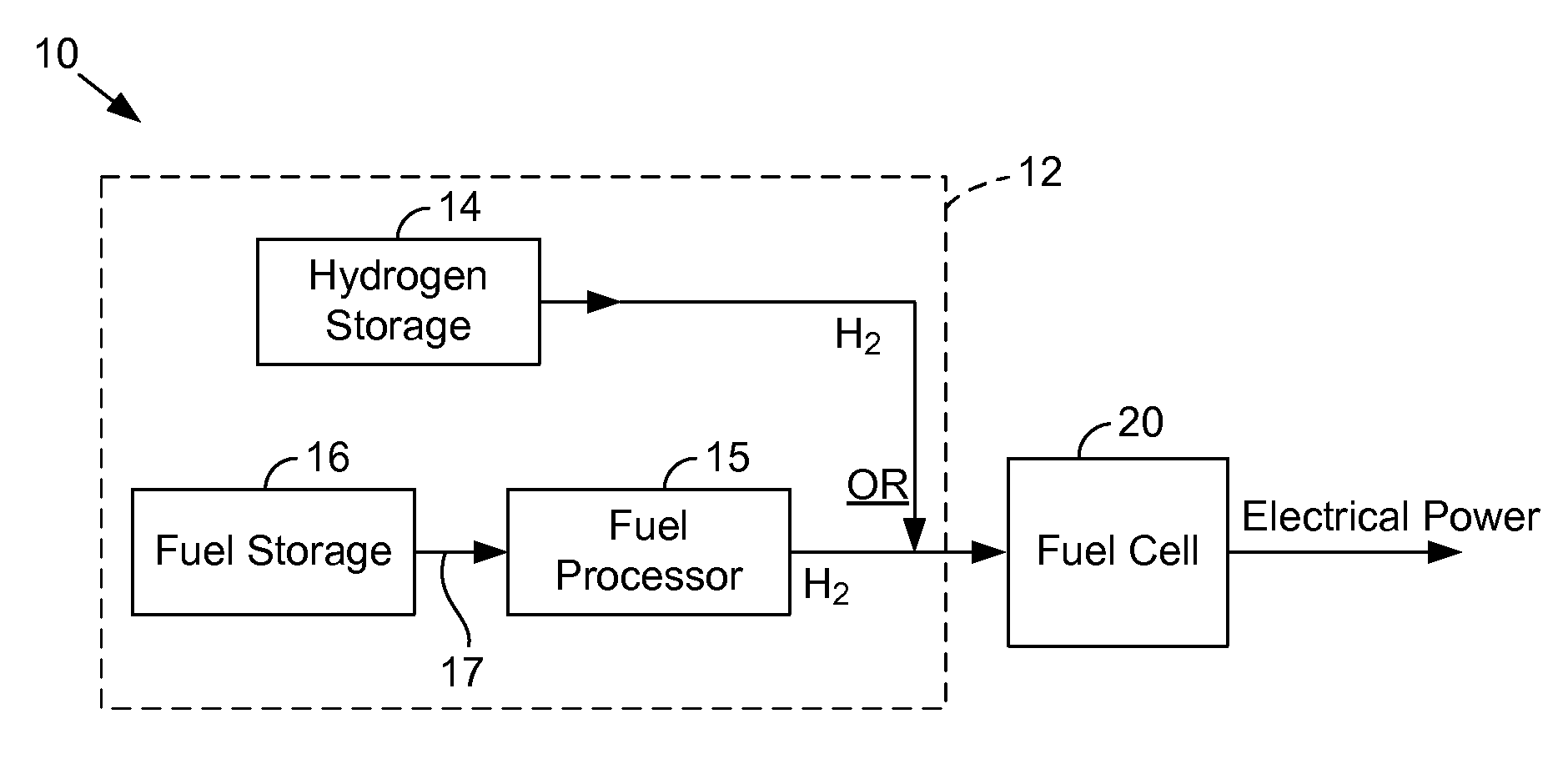
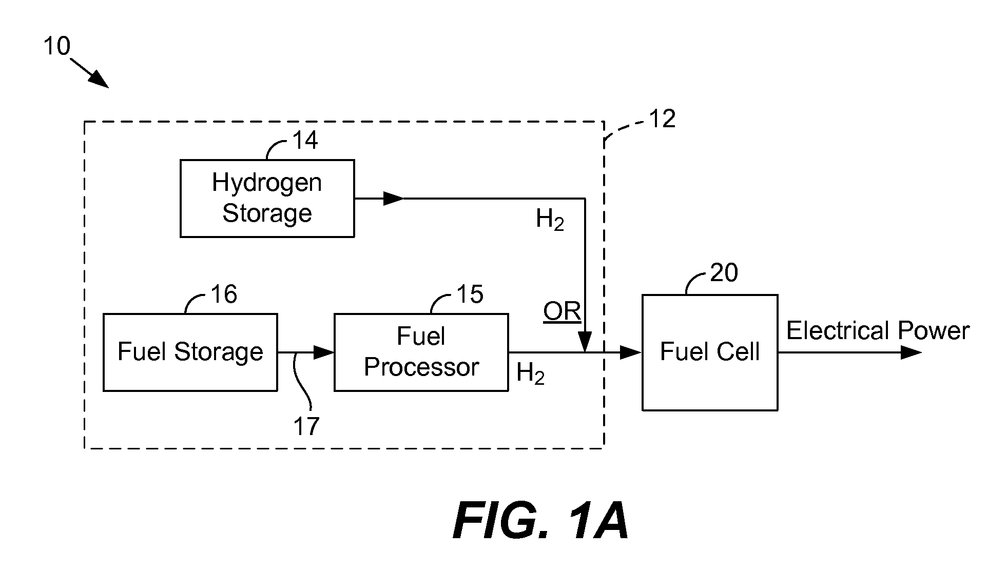
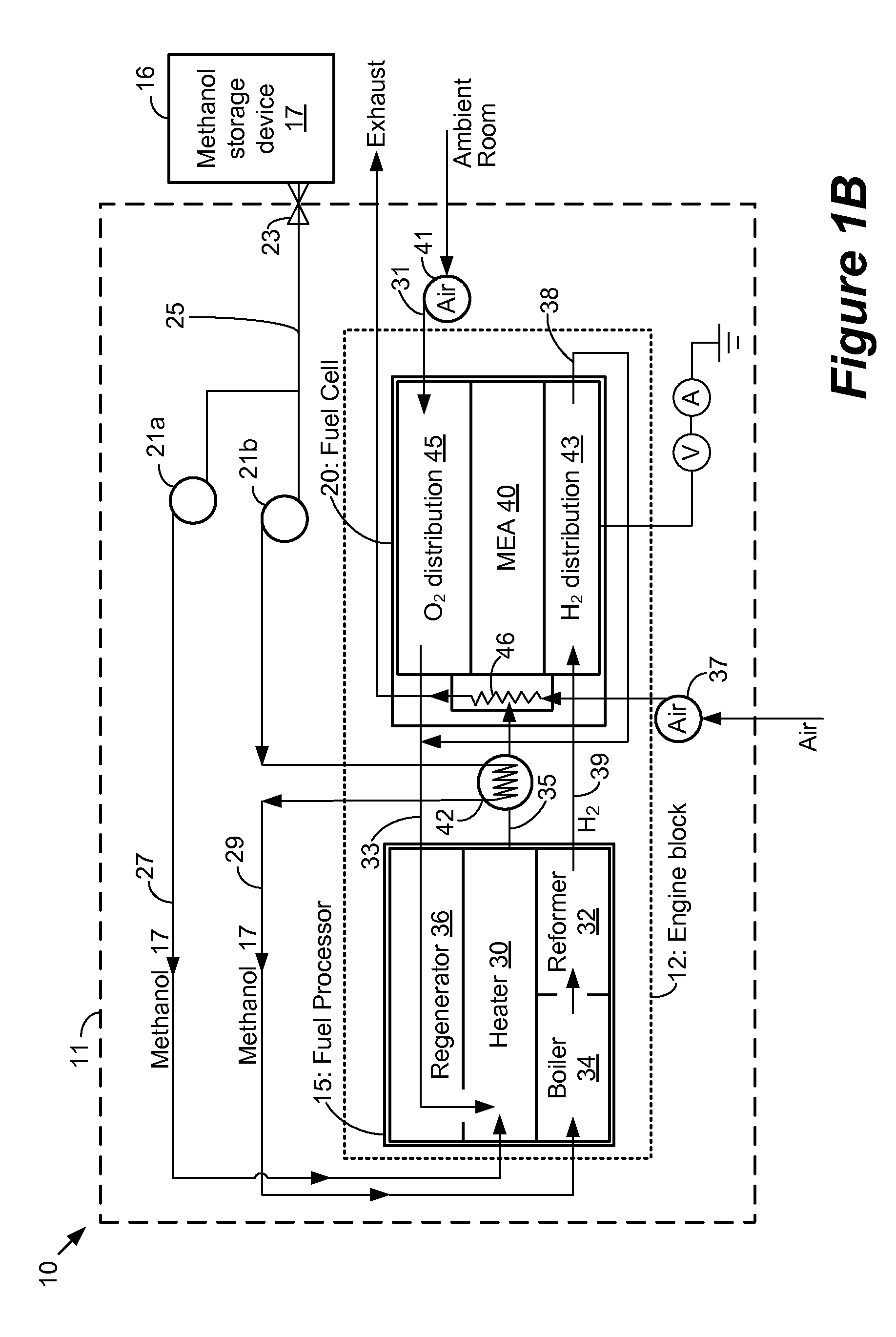
[0026]Embodiments are described herein in the context of an engine block for use in a fuel cell system. The following detailed description is illustrative only and is not intended to be in any way limiting. Other embodiments will readily suggest themselves to such skilled persons having the benefit of this disclosure. Reference will now be made in detail to implementations as illustrated in the accompanying drawings. The same reference indicators will be used throughout the drawings and the following detailed description to refer to the same or like parts.

[0027]In the interest of clarity, not all of the routine features of the implementations described herein are shown and described. It will, of course, be appreciated that in the development of any such actual implementation, numerous implementation-specific decisions must be made in order to achieve the developer's specific goals, such as compliance with application- and business-related constraints, and that these specific goals w...


PUM

PropertyMeasurementUnit
temperatureaaaaaaaaaa
poweraaaaaaaaaa
poweraaaaaaaaaa

Abstract

In one embodiment, an engine block may comprise an interconnect having: a first manifold section, a second manifold section perpendicular to the first manifold section, the first manifold section and the second manifold section having a plurality of conduits to receive a gas flow, wherein the first manifold section and the second manifold section are formed from a single manifold device; a fuel cell stack housing coupled to the second manifold section to receive a fuel cell stack; and a fuel processor coupled to the first manifold section, wherein the fuel cell processor and the fuel cell stack operate at substantially the same temperature.

Description

CROSS REFERENCE TO RELATED APPLICATIONS[0001]This application claims priority under 35 U.S.C. §119(e) to U.S. Provisional Patent Application No. 60 / 836,896, filed on Aug. 9, 2006 entitled “PORTABLE FUEL CELL SYSTEMS”, which is incorporated by reference for all purposes.[0002]This application also claims priority under 35 U.S.C. § 119(e) to U.S. Provisional Patent Application No. 60 / 836,859, filed on Aug. 9, 2006 entitled “FUEL PROCESSOR FOR USE IN A FUEL CELL SYSTEM”, which is incorporated by reference for all purposes.FIELD OF THE INVENTION[0003]The present disclosure relates generally to fuel cell technology. In particular, the invention relates to an engine block, used in a fuel cell system, to convert hydrogen to electrical energy.BACKGROUND OF THE INVENTION[0004]A fuel cell electrochemically combines hydrogen and oxygen to generate electrical energy. Fuel cell development so far has only serviced large-scale applications such as industrial size generators for electrical power b...

Claims


Application Information

Patent Timeline
Patent Type & Authority Applications(United States)
IPC IPC(8): H01M8/06H01M8/04H01M8/00
CPCB01J23/40Y10T29/49108C01B3/0005C01B3/323C01B2203/0233C01B2203/066C01B2203/0811C01B2203/0822C01B2203/0827C01B2203/1064C01B2203/1076C01B2203/1223C01B2203/1288H01M8/04007H01M8/04037H01M8/0625H01M8/2475H01M8/2485Y02E60/324Y02E60/50B01J35/04Y02P20/52Y02E60/32Y02P20/10B01J35/56
Inventor BRANTLEY, JENNIFERNEWELL, KENNETHKASCHMITTER, JAMES L.SOPCHAK, DAVIDKAYE, IAN W.SOMOGYVARI, ARPADBEDNAROVA, LUCIEDERENZI, MICHAEL C.
Owner ULTRACELL ACQUISITION
Learn More