
Process to preserve isopipe during coupling

a technology of isopipes and couplings, applied in glass rolling apparatus, glass tempering apparatus, manufacturing tools, etc., can solve problems such as limiting their useful life, and achieve the effect of reducing the tensile stress of isopipes during us

Active Publication Date: 2008-08-28
CORNING INC
View PDF6 Cites 27 Cited by
  • Summary
  • Abstract
  • Description
  • Claims
  • Application Information

AI Technical Summary

Benefits of technology

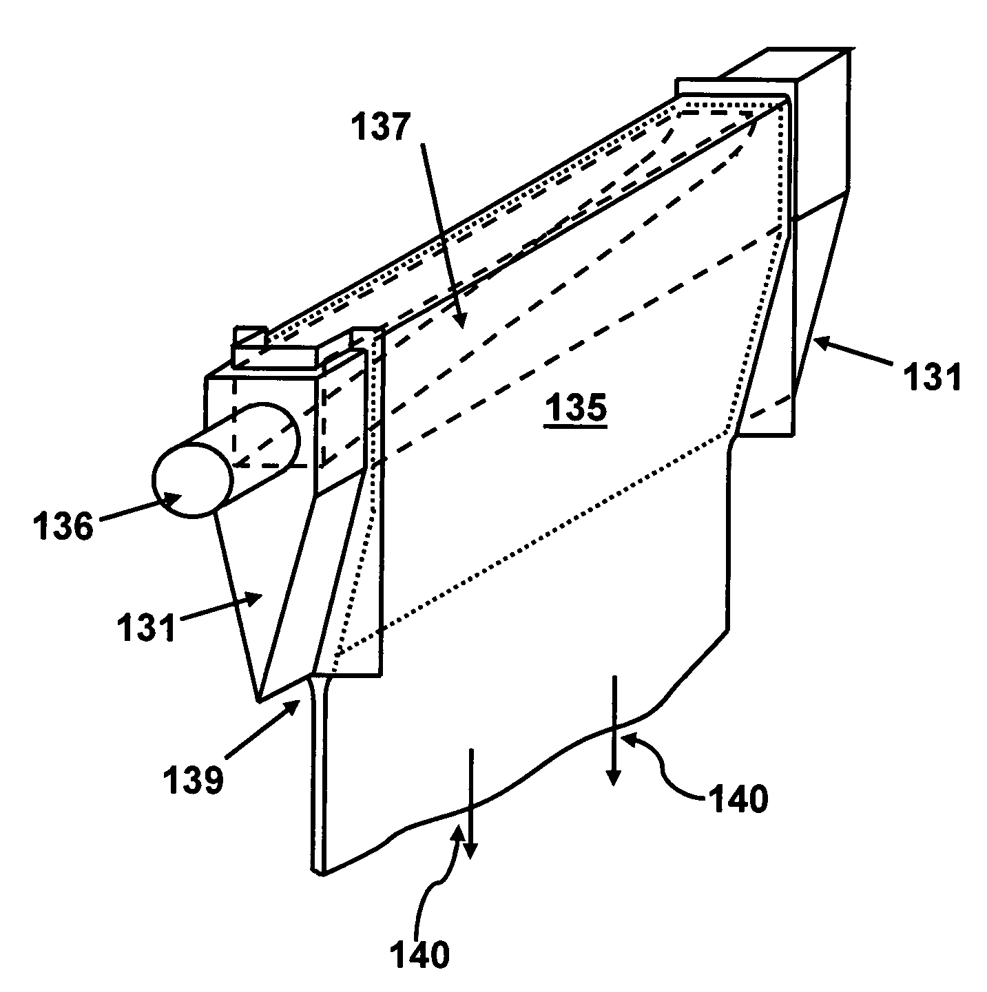
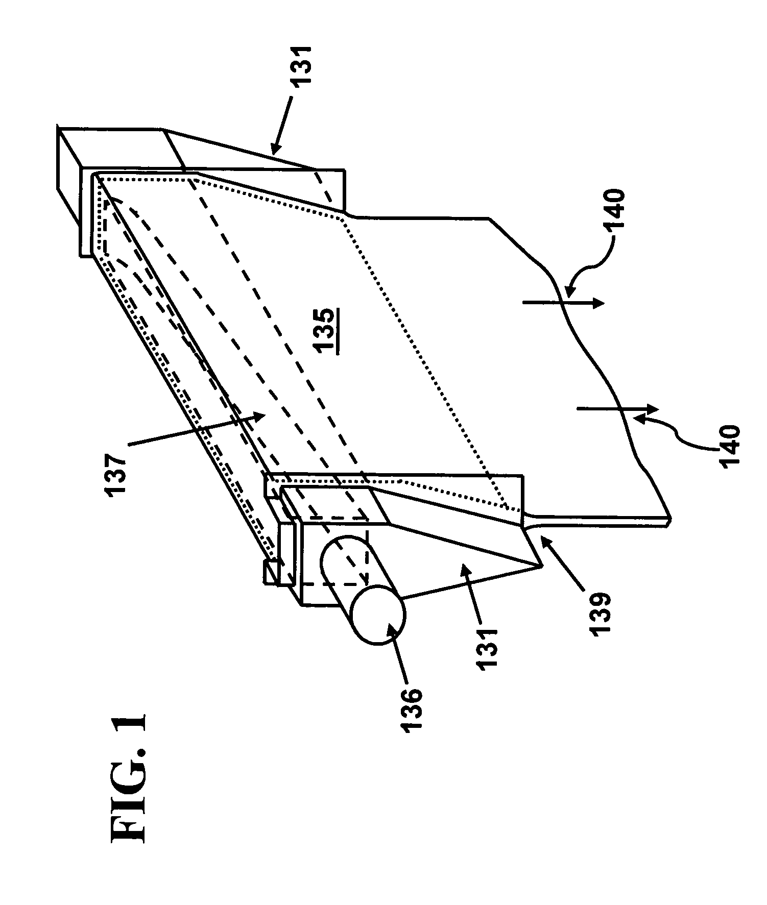
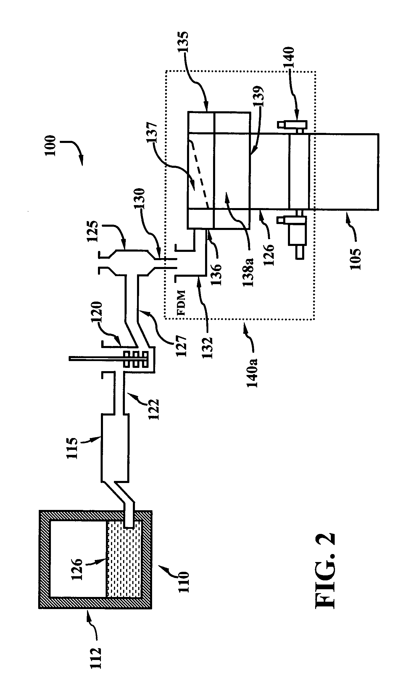
[0013]In a first aspect, the present invention provides a method for reducing stress on an isopipe during manufacture of a drawn glass sheet, the method comprising:
[0026]A second aspect of the present invention is a method for reducing stress on an isopipe during manufacture of a drawn glass sheet, the method comprising:
[0034]A third aspect of the present invention is a method for reducing stress on an isopipe during manufacture of a drawn glass sheet, the method comprising:

Problems solved by technology

Even with such high performance materials, isopipe materials can fracture or creep, resulting in dimensional changes which limit their useful life.

Method used


Image

  • Process to preserve isopipe during coupling
  • Process to preserve isopipe during coupling
  • Process to preserve isopipe during coupling

Examples


example 1

Typical Heat-Up and Coupling Process

[0094]In a first example, a zircon isopipe subjected to a typical heating schedule, as illustrated in FIG. 3, is modeled. In this figure, MRTS means maximal root tensile stress. As the isopipe is heated and the temperature difference between the weir and the root increases, the tensile stress on the isopipe root also increases to about 1,600 psi. At the end of the heating schedule, the isopipe is coupled to the down-corner, resulting in a temperature drop at the root of about 60° C. This quick temperature change results in an increase in the root tensile stress of about 2,100 psi (i.e., from about 1,600 psi to about 3,700 psi).

example 2

Incorporation of a Temperature Hold

[0095]In a second example, a zircon isopipe initially heated as in Example 1 is modeled, but prior to coupling the isopipe to the down-corner, the temperature is maintained for a period of 33 hours (FIG. 4, period shown as “HP”). While the temperature difference between the weir and the root is not significantly different from the heating schedule of Example 1, the maximum tensile stress on the isopipe, during coupling, is approximately 2,600 psi when a temperature hold is used, compared to 3,700 psi in the absence of a temperature hold.

example 3

Reduction of Delta Temperature Prior to Coupling

[0096]In a third example, a zircon isopipe initially heated as in Example 1 is modeled, but the heating schedule is modified such that the temperature difference between the weir and the root at the end of the heating schedule and prior to coupling is reduced to 60° C. FIG. 5 illustrates the difference in maximum root tensile stress between this heating schedule and the heating schedule presented in Example 2 (with 33 hour temperature hold). The tensile stress at the end of the modified heating schedule and prior to coupling is less than 500 psi.


PUM

PropertyMeasurementUnit
Temperatureaaaaaaaaaa

Abstract

Methods for reducing stress on an isopipe during manufacture of a drawn glass sheet are disclosed including a method comprising providing an isopipe having a root, heating the isopipe to a predetermined temperature, maintaining the isopipe at the predetermined temperature for a period of time sufficient to relieve at least a portion of a tensile stress on the isopipe root, coupling the isopipe to a down-corner, and then providing glass to the isopipe. Also disclosed is a method comprising heating an isopipe such that the temperature difference between the weir and the root of the isopipe, after heating and prior to coupling, is less than about 100° C. A method comprising application of a compressive force to the ends of an isopipe root during heating is also disclosed.

Description

CROSS-REFERENCED TO RELATED APPLICATIONS[0001]This application claims the benefit of priority under 35 U.S.C. §119(e) of U.S. Provisional Application Ser. No. 60 / 902,666 filed on Feb. 22, 2007.BACKGROUND[0002]1. Field[0003]The present invention relates to apparatuses and methods used in the manufacture of sheet glass by the fusion process.[0004]2. Technical Background[0005]The fusion process is one of the basic techniques used to produce sheet glass and can produce sheet glass having surfaces with superior flatness and smoothness relative to sheet glass produced by alternative processes, such as for example, the float and slot drawn processes. As a result, the fusion process has found advantageous use in the production of the glass substrates used in the manufacture of light emitting displays, such as liquid crystal displays (LCDs).[0006]The fusion process, specifically, the overflow downdraw fusion process, includes a supply pipe, known as an isopipe, which provides molten glass to...

Claims


Application Information

Patent Timeline
IPC IPC(8): C03B17/06
CPCC03B17/064C03B25/00
Inventor HOYSAN, STEVEN F.MILILLO, STEVEN MICHAELPOWELL, WILLIAM ROBERT
Owner CORNING INC
Learn More