
Method for Welding a Sintered Shaped Body

Inactive Publication Date: 2008-08-21
MIBA SINTER AUSTRIA
View PDF8 Cites 0 Cited by
  • Summary
  • Abstract
  • Description
  • Claims
  • Application Information

AI Technical Summary

Benefits of technology

[0008]When choosing the deoxidizer it is necessary to ensure that the binding energy towards oxygen is higher than towards the alloy elements of the sintered molded body. Furthermore, no disadvantageous effects on the properties of the weld seam should occur by the incorporation in the weld seam of the formed oxides. When silicon and / or titanium or one of their compounds are used as a deoxidizer in connection with steel sintered materials, these conditions can be fulfilled in an advantageous manner. Especially silicon counteracts an embrittlement of the weld seam and extends the weldability towards higher carbon contents of the sintered steel.
[0009]When the molded body is welded with the help of a defocused laser beam, the sintered material is molten in a higher width with the effect that melt can continue to flow from the boundary region to the depth of the weld seam, thus allowing for a favorable weld connection over the required weld depth. Notice must be taken in this connection that as a result of the residual porosity of the sintered molded body a reduction in the volume in the area of the weld seam is obtained after the solidification of the molten sintered material.
[0010]The joining of sintered molded bodies by welding requires dry subjects which are free from oil and grease in the area of the weld seam. In order to avoid having to fear any enrichment of oxygen in the pores of the cleaned surfaces during the cleaning of the molded body in preparation of the welded connection, the sintered molded body can be cleaned prior to welding by a heat treatment in a reducing protective gas atmosphere or in a low-oxygen atmosphere. Oil-free and grease-free surfaces of the sintered molded body can be obtained by annealing under a reducing protective gas or by flashing off under deficiency of air without introducing additional atmospheric oxygen into the cleaned pores.

Problems solved by technology

It has been seen however that the weld seams which are obtained by melting of the sinter material by a laser beam have a comparatively high porosity and therefore do not meet higher requirements placed on the strength.

Method used


Image

  • Method for Welding a Sintered Shaped Body
  • Method for Welding a Sintered Shaped Body
  • Method for Welding a Sintered Shaped Body

Examples


Embodiment Construction

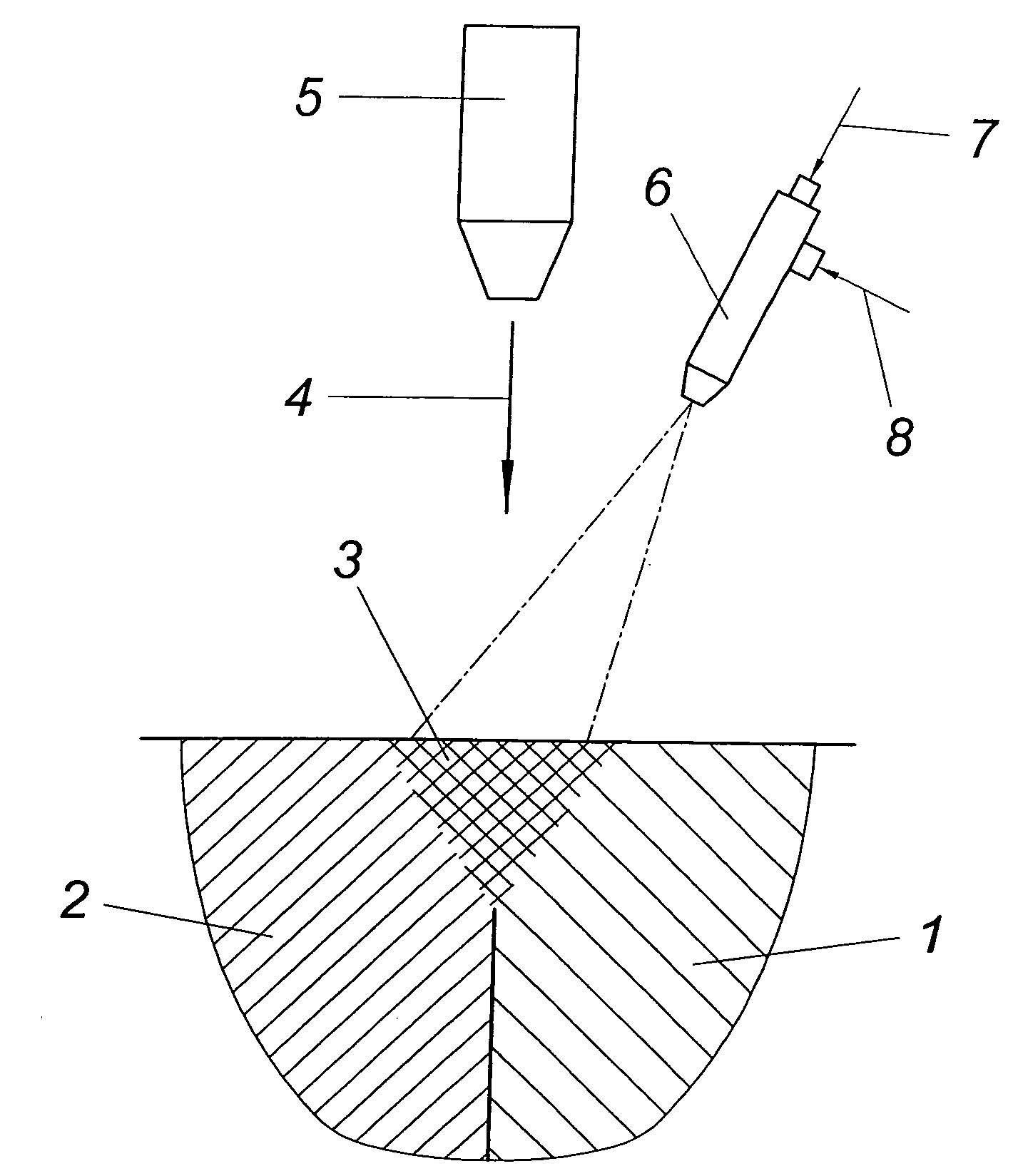
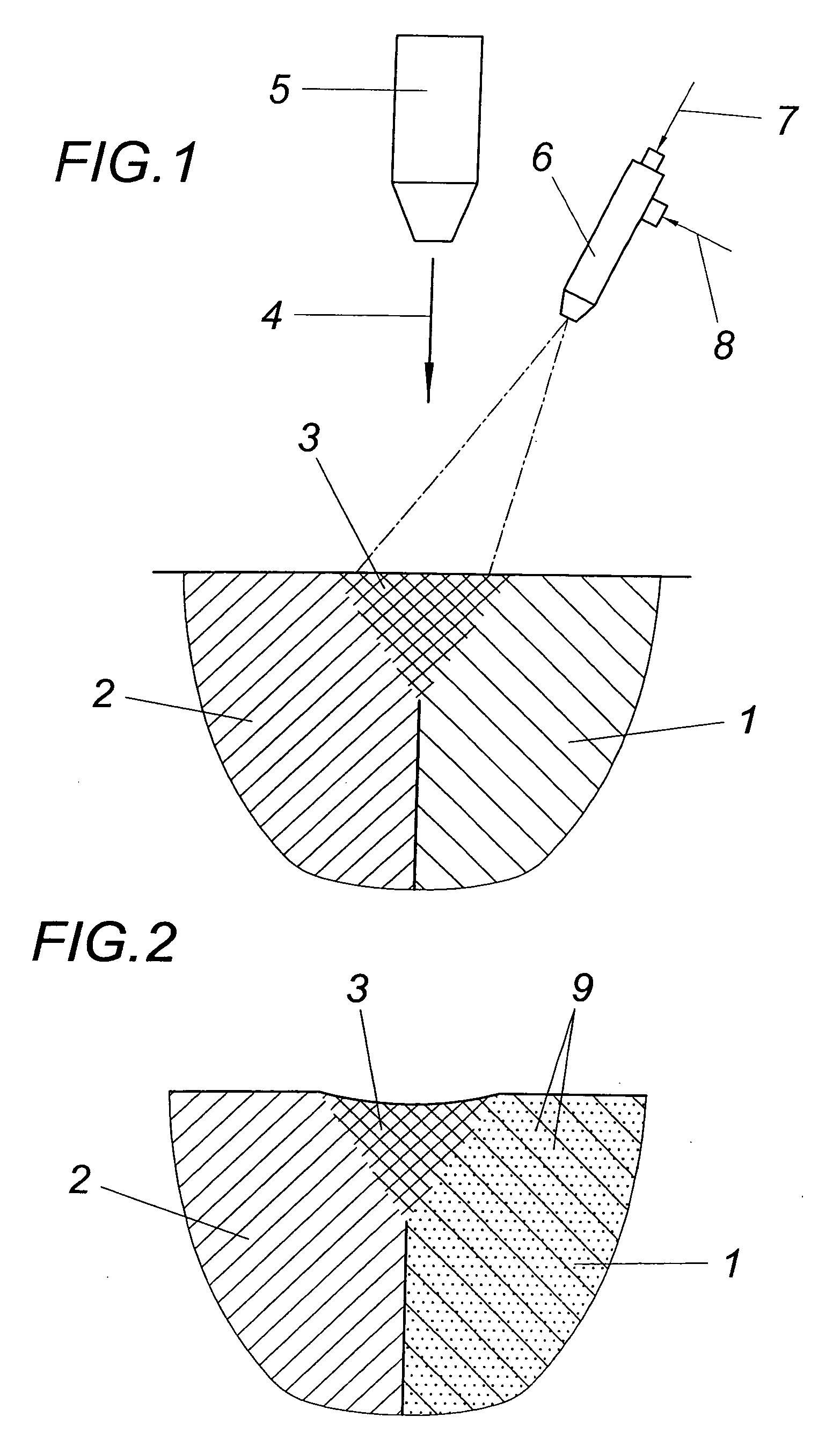
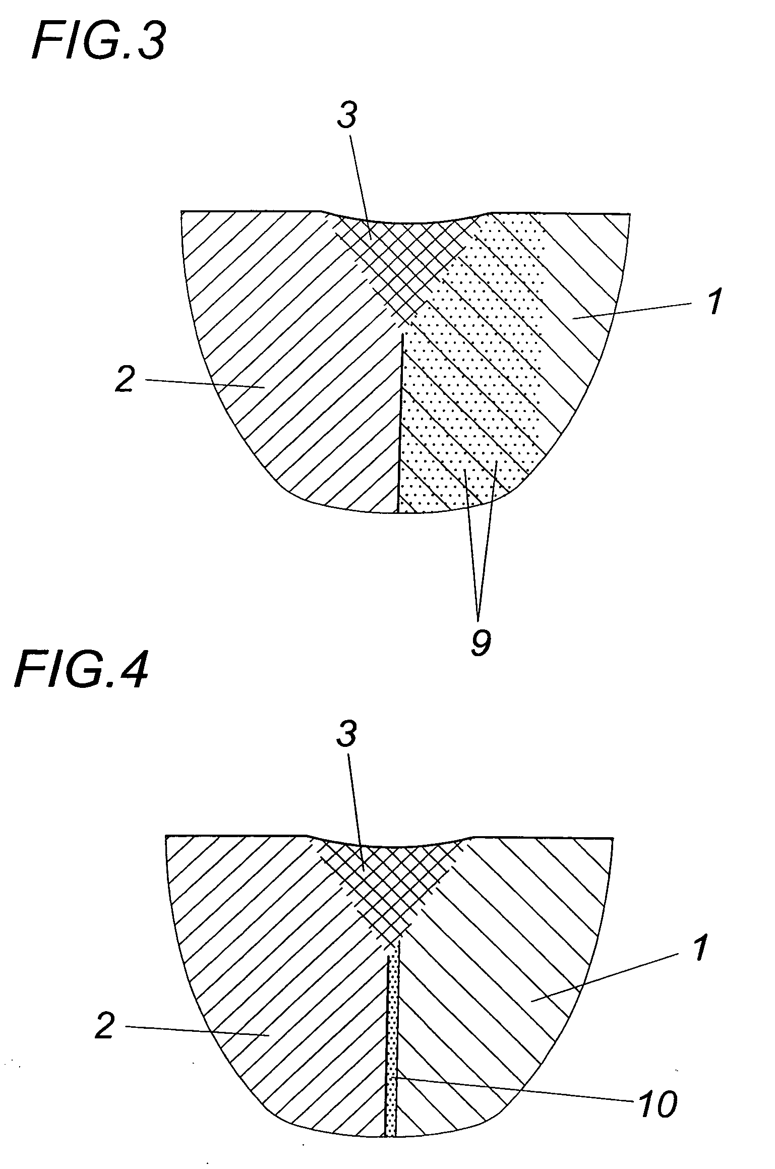
[0016]According to the illustrated embodiment, a sintered molded body 1 is joined to a non-sintered component 2 by means of welding, such that the materials of the sintered molded body 1 and the non-sintered component 2 are fused in the region of the later weld seam 3 by a preferably defocused laser beam 4 of a laser head 5, as is shown in FIG. 1. Since during the melting of the sintered material of the molded body 1 the atmospheric oxygen from the pores of the molded body 1 produces a foaming of the melt, a porous weld seam is obtained, unless special precautions are taken in order to prevent the foaming of the melt. For this purpose a deoxidizer is used which reacts with the atmospheric oxygen from the pores of the molded body 1 during the melting of the sintered material and forms oxides which are incorporated into the weld seam 3 in a finely dispersed manner without impairing the strength of the weld seam 3. By using a respective oxidizer, dense weld seams 3 can be obtained whic...


PUM

PropertyMeasurementUnit
Areaaaaaaaaaaa
Melting pointaaaaaaaaaa
Porosityaaaaaaaaaa

Abstract

A method is described for welding a sintered molded body (1) which comprises a residual porosity and which is molten in the region of the later weld seam (3) by a laser beam (4). In order to obtain dense weld seams it is proposed that during the melting of the molded body (1) the atmospheric oxygen is bound at least substantially by a deoxidizer from the pores of the molded body (1) in the area of the weld seam and is embedded in the form of finely dispersed oxides in the weld seam (3).

Description

1. FIELD OF THE INVENTION[0001]The invention relates to a method for welding a sintered molded body which comprises a residual porosity and which is molten in the region of the later weld seam by a laser beam.2. DESCRIPTION OF THE PRIOR ART[0002]Molded bodies made of sintered steel can principally be joined to other steel components by welding, which occurs irrespective of whether or not such components were produced by means of powder metallurgy. It has been seen however that the weld seams which are obtained by melting of the sinter material by a laser beam have a comparatively high porosity and therefore do not meet higher requirements placed on the strength.SUMMARY OF THE INVENTION[0003]The invention is thus based on the object of providing a method for welding a sintered molded body with residual porosity with the help of a laser beam of the kind mentioned above in such a way that in joining two weldable components, of which at least one comprises a sintered molded body, weld s...

Claims


Application Information

Patent Timeline
IPC IPC(8): B23K26/12B23K26/14B23K26/32B23K35/30
CPCB22F2999/00B23K26/123B23K26/1411B23K26/3206B23K35/3053B23K2203/02B22F7/062B22F2202/11B23K26/32B23K26/144B23K2103/02B23K2103/50
Inventor ORTH, PETERRATZI, RAIMUND
Owner MIBA SINTER AUSTRIA
Learn More