
Fuel processor for fuel cell systems

a fuel processor and fuel cell technology, applied in sustainable manufacturing/processing, electrochemical generators, lighting and heating apparatus, etc., can solve the problems of shocks that can only carbon monoxide cannot be used as fuel, and the reaction to the heating process is relatively slow, so as to achieve a small temperature gradient

Inactive Publication Date: 2008-08-07
SILICON VALLEY BANK
View PDF33 Cites 54 Cited by
  • Summary
  • Abstract
  • Description
  • Claims
  • Application Information

AI Technical Summary

Benefits of technology

"The patent describes a portable and fuel cell system that uses a fuel reformer to convert liquid or gaseous fuel to a hydrogen-rich stream. The fuel processor includes a heat transfer block, vaporizer, and heating element for starting up the system. The technology allows for a cold start of the fuel processor by activating the heating element to heat the block and monitoring the temperature. The method also involves using a pump to generate the hydrogen output stream and a burner to continuously heat the block. The technical effects of the patent include a compact, lightweight, and efficient fuel processor for fuel cells."

Problems solved by technology

Common fuels are hydrogen, methanol, and carbon monoxide; however, carbon monoxide can only be used as a fuel in high-temperature fuel cells operating at temperatures >400° C. The most common oxidant is oxygen, either in a relatively pure form or from air.
Mechanical events such as vibrations and shocks can break down the bed.
Often, channels form that undesirably create flowpaths that allow the fuel stream to pass without significant reaction.
Due to the large size and wall thickness of the tubes, the reaction to the heating process is relatively slow (i.e., an undesirable gradient occurs).
Further, the bed can break down during this thermal cycling.
Because the microchannels are so small, a bulk material cannot be used as a catalyst.
Unfortunately, the microchannel technology is expensive to manufacture and heavy as a large amount of a metal such as steel is necessary.

Method used


Image

  • Fuel processor for fuel cell systems
  • Fuel processor for fuel cell systems
  • Fuel processor for fuel cell systems

Examples


Embodiment Construction

[0032]As used herein, the term “about” when used in reference to a numerical value means the indicated numerical value +10% of that value.

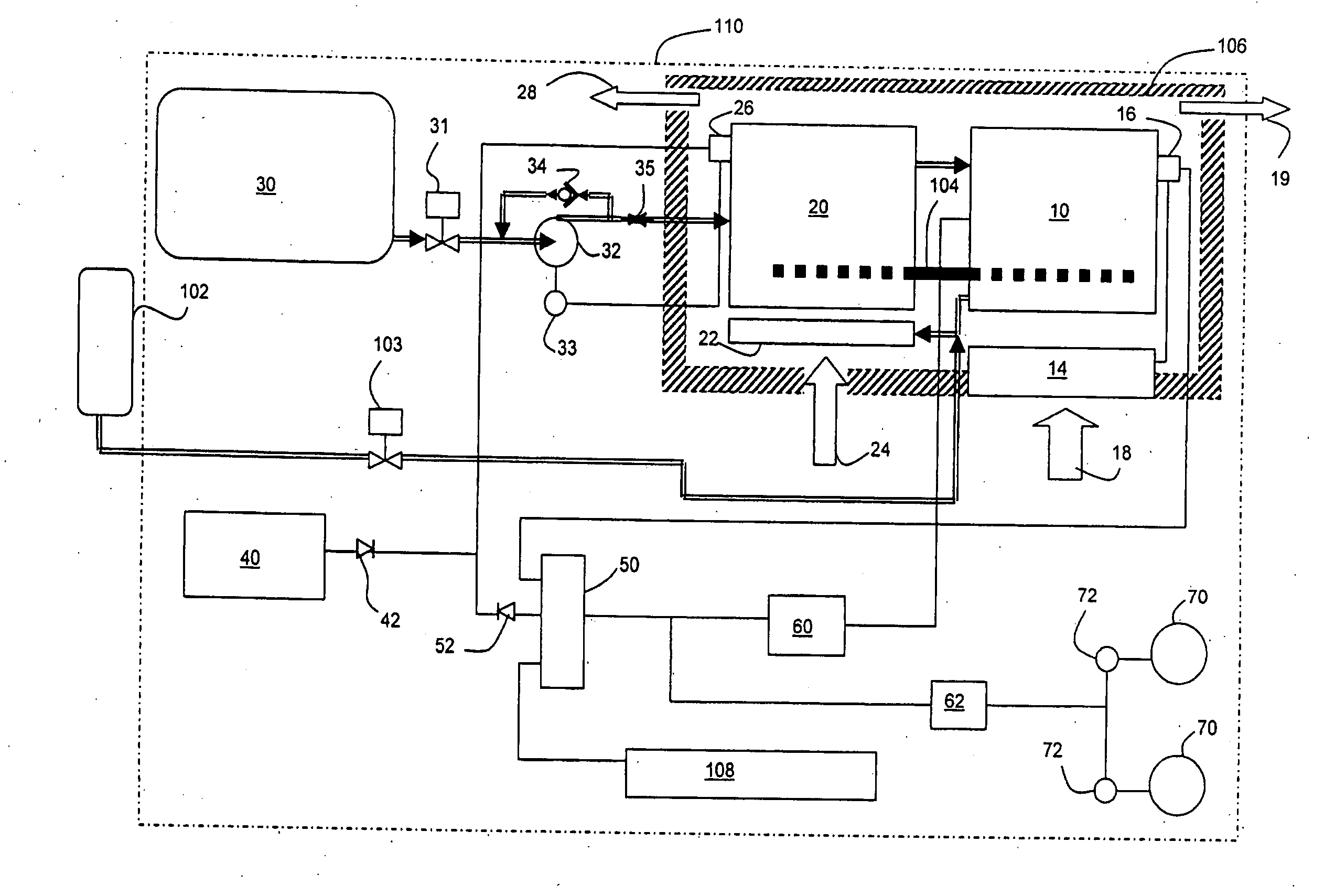
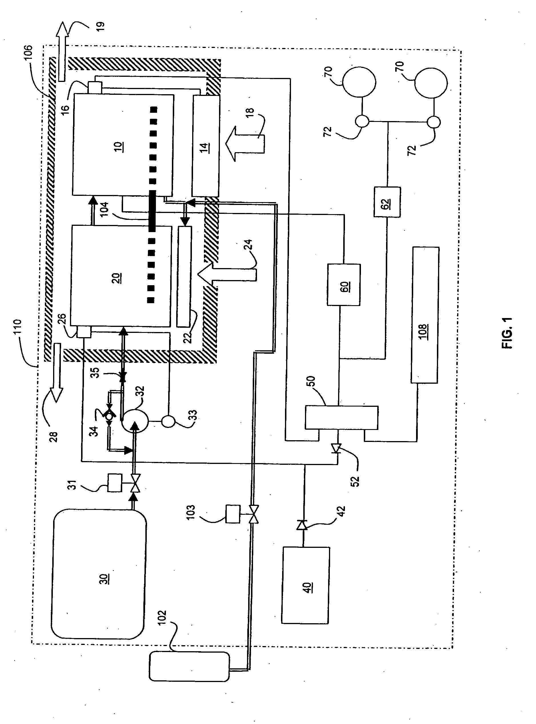
[0033]An exemplary embodiment of the invention is shown schematically in FIG. 1, the system comprising fuel cell stack 10, at least one fuel cell cooling fan 14, fuel cell thermal switch 16, fuel cell air feed 18 and fuel cell combustion exhaust duct 19. The system further comprises fuel reformer 20 operatively coupled to fuel cell stack 10, fuel reformer burner 22, fuel reformer air feed 24, fuel reformer thermal switch 26 and fuel reformer combustion exhaust duct 28. One or more heat pipes 104 pass from the vicinity of the fuel reformer burner 22 into the fuel cell stack 10. Fuel reformer 20 is fed fuel from fuel reservoir 30 via fuel reservoir shut off valve 31, fuel reservoir fuel pump 32, fuel pump switch 33, fuel check valve 34 and fuel feed orifice 35.

[0034]All of the system's components with the exception of a fuel tank 102 for supplying f...


PUM

PropertyMeasurementUnit
interior diameteraaaaaaaaaa
temperaturesaaaaaaaaaa

Abstract

A fuel processor assembly for producing a hydrogen rich stream for a fuel cell includes a reformer, a vaporizer adjacent the reformer, a heat transfer block around at least a portion of the reformer and the vaporizer and a heating element coupled to the heat transfer block for providing heat to the block during start up. To cold start the fuel processor, the heating element is activated to heat the heat transfer block. When a temperature of the heat transfer block reaches operational for the reformer, the heating element is turned off and an alternative source of heat is utilized for the endothermic reaction.

Description

CROSS-REFERENCE TO RELATED APPLICATION[0001]This application claims priority to and is a continuation-in-part of U.S. patent application Ser. No. 11 / 484,514, filed Jul. 6, 2007, which is incorporated herein by reference.BACKGROUND OF THE INVENTION[0002]Fuel cells are electrochemical devices that produce direct current (DC) electricity by the reaction of a fuel with an oxidant, typically producing byproducts of heat and water. Common fuels are hydrogen, methanol, and carbon monoxide; however, carbon monoxide can only be used as a fuel in high-temperature fuel cells operating at temperatures >400° C. The most common oxidant is oxygen, either in a relatively pure form or from air. Fuel cells contain an anode, a cathode, and an electrolyte barrier between the anode and cathode. The fuel is introduced at the anode and the oxidant is introduced at the cathode. The electrolyte barrier, commonly referred to as a membrane-electrode assembly or MEA, is an ionically conductive thin barrier ...

Claims


Application Information

Patent Timeline
Patent Type & Authority Applications(United States)
IPC IPC(8): H01M8/06B01D1/02B23P15/26F28F9/02
CPCC01B3/323Y10T29/4935C01B2203/066C01B2203/0822C01B2203/0827C01B2203/1223C01B2203/1288C01B2203/1604H01M8/04268H01M8/04365H01M8/04373H01M8/04738H01M8/04955H01M8/0625Y02E60/50C01B2203/0233F28D15/0275Y02P20/10
Inventor EDLUND, DAVID
Owner SILICON VALLEY BANK
Learn More