
Micron-scale implantable transponder

Inactive Publication Date: 2008-07-31
DESTRON FEARING CORP
View PDF26 Cites 43 Cited by
  • Summary
  • Abstract
  • Description
  • Claims
  • Application Information

AI Technical Summary

Benefits of technology

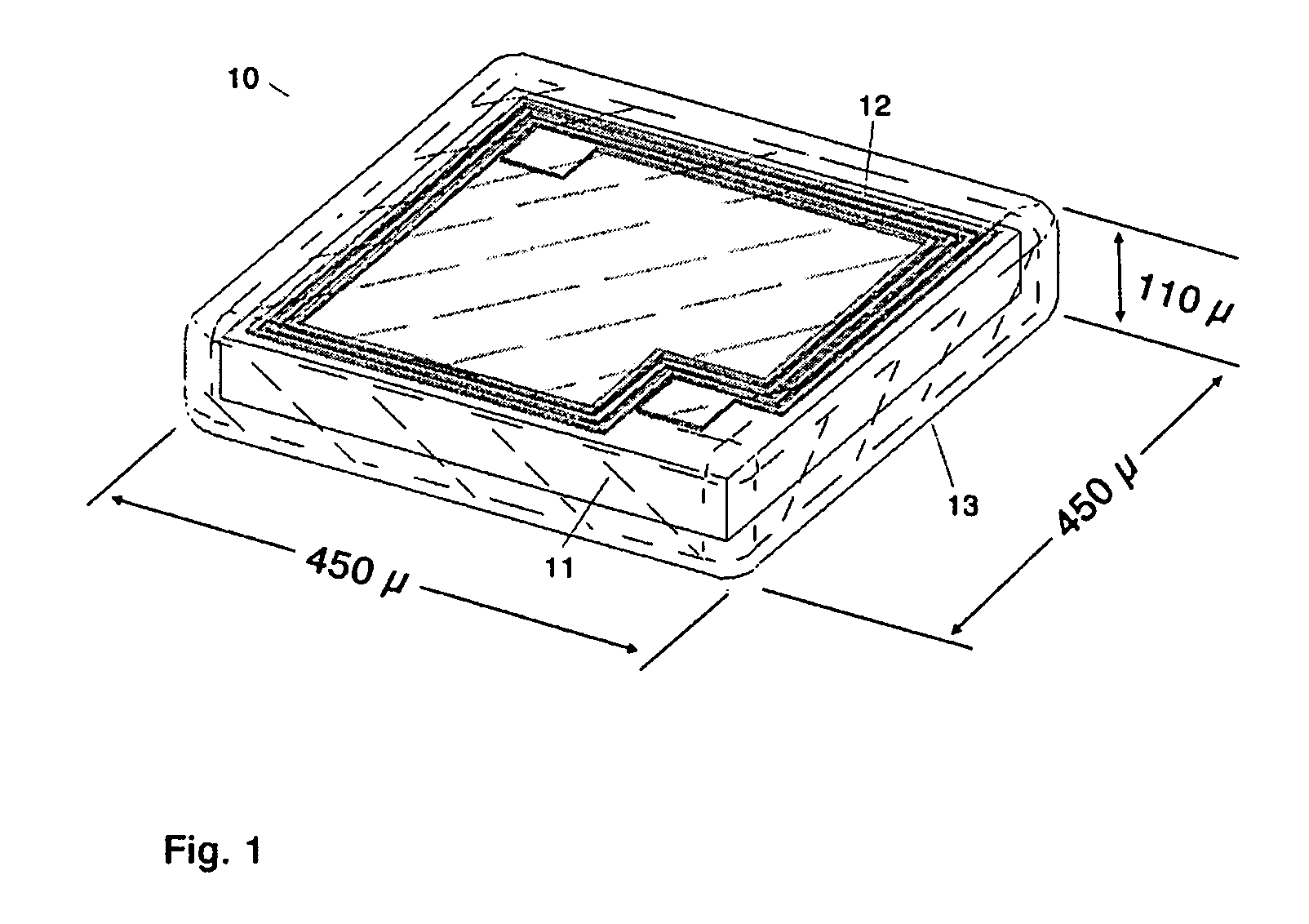
[0013]In view of the above discussion and the shortcomings of the present implantable RFIDs, the present invention seeks to overcome such shortcomings by creating an implantable RFID transponder, which is preferably more than a thousand times smaller in volume than prior art implantable RFIDs. In one embodiment of the present invention, an implantable RFID is provided, which is only 110 microns (110×10−6 meters) thick and by virtue of which can be implanted in the dermis (skin) of the patient rather than under the dermis thereby reducing implantation trauma and preferably does not migrate from the implantation location.
[0014]In one embodiment of the present invention, an implantable RFID is disclosed which is preferably completely integrated and which contains no discrete parts. In another embodiment, the RFID is completely solid and has zero void volumes thereby eliminating or hindering the risk of accumulation of diffused H2O upon the integrated circuit.
[0015]In another embodiment of the present invention, a polymeric encapsulation, which is a barrier to ions, is used in making the RFID to eliminate the risk of corrosion of the integrated circuit. In yet another embodiment, a biocompatible conformal coating is applied directly to the integrated circuit die to maintain substantial decrease in volume. Moreover, in the RFID according to one embodiment of the present invention, a ferrite-free, integrated antenna is formed by the process used for under-bump metallization, where gold, titanium, aluminum, nickel-vanadium, copper or other suitable metal is sputtered, or conductive paste screened, onto the surface of the integrated circuit to form an antenna.
[0016]According to one embodiment of the present invention, the implantable RFID operates at gigahertz frequencies that reduce the required size of the antenna allowing it to be formed as part of the integrated circuit chip. In yet another embodiment, the RFID is glass free and which, by virtue of its polymeric conformal coating is substantially unbreakable compared to prior art glass and glass-equivalent encapsulated implantable RFIDs.

Problems solved by technology

While prior art RFIDs are sometimes referred to as “integrated”, they are not actually fully integrated in the sense of an ‘integrated circuit chip’ but rather consist of multiple discrete parts.
While prior art implantable RFID transponders may function and be appropriate for certain animals, they are nevertheless less than optimal when considered for implantation in humans, other animals or objects because they are still relatively large devices to implant.
A 12 gauge implantation needle creates a significant wound track, may leave a scar, puts the patient at risk for infection and can cause the implantation to be painful.

Method used


Image

  • Micron-scale implantable transponder
  • Micron-scale implantable transponder
  • Micron-scale implantable transponder

Examples


Embodiment Construction

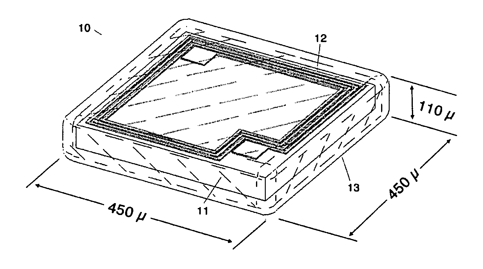
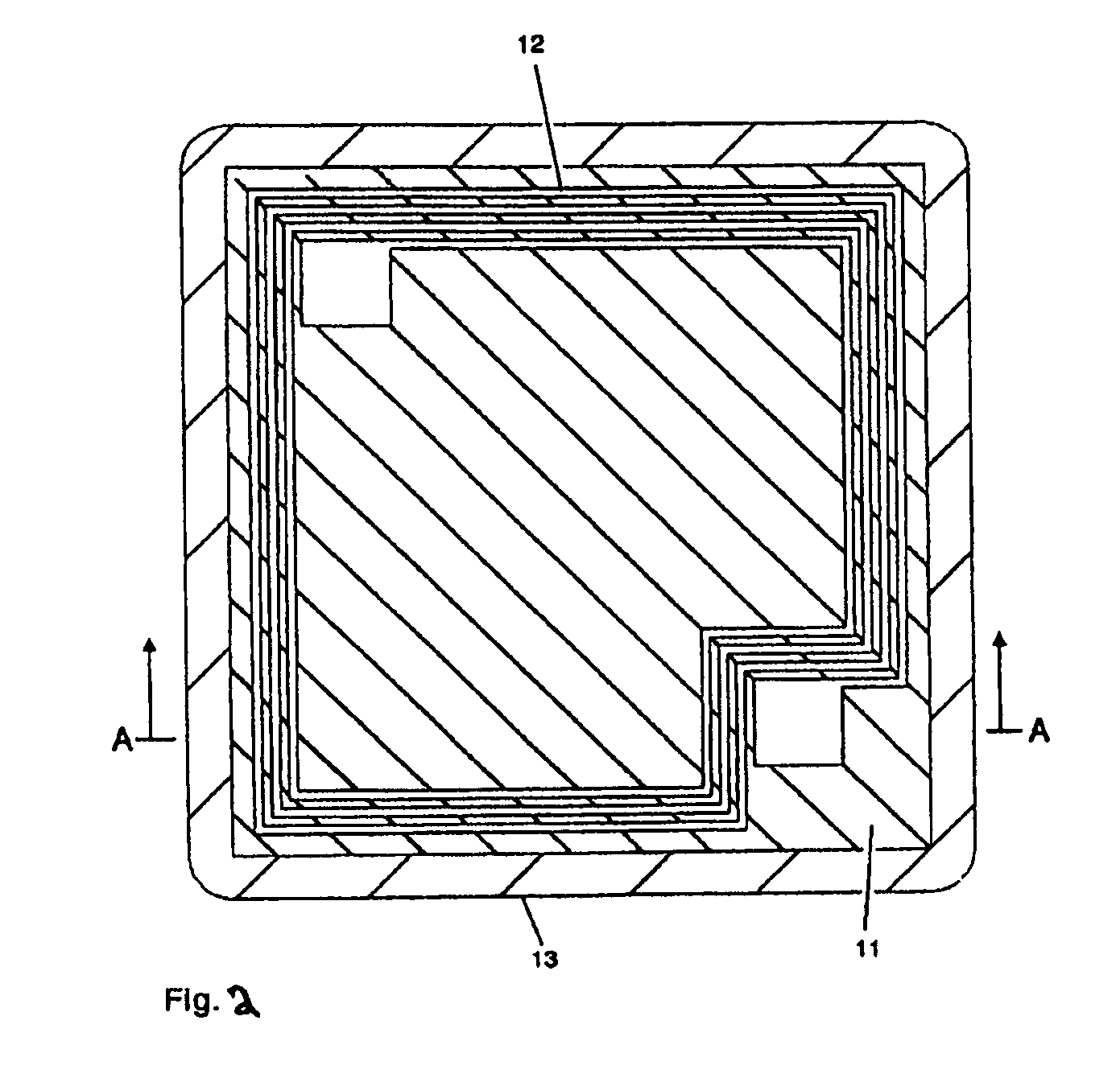
[0036]Referring to FIGS. 1, 2 and 3, a micro sized implantable RFID 10 is shown that is composed of an integrated circuit die 11 with integrated antenna 12, and biocompatible conformal coating 13. As shown in FIG. 2 and FIG. 3, the integrated antenna 12 is a metallic antenna deposited directly onto the integrated circuit die 11 by sputtering gold, silver, titanium, aluminum, nickel-vanadium, copper, or other suitable metals, either individually or in combinations, such as Al / NiV / Cu, or screening conductive paste which includes copper, palladium, or gold particles suspended in an organic binder, liquid carrier or polyimide upon the surface of the integrated circuit die 11 using the same process used for under-bump metallization of integrated circuits. Under-bump metallization, either by sputtering or screening, is a process well known in the art. One such example is in U.S. Pat. No. 6,992,001 entitled “Screen Print Under-Bump Metalization (UBM) To Produce Low Cost Flip Chip Substrate...


PUM


Abstract

A miniaturized implantable transponder in which all components, including the antenna, are fully integrated into a single microchip that has a conformal coating that consists of a polymeric substance that is applied by vapor deposition techniques resulting in reduced volume versus the typical implantable transponder and reduces the volume size of the typical implantable transponder to enable easier implantation in a patient virtually eliminating implantation trauma in a patient.

Description

CROSS REFERENCE TO RELATED APPLICATION[0001]This application claims the benefit of provisional application Ser. No. 60 / 898,262 filed on Jan. 29, 2007 entitled “MICRON-SCALE IMPLANTABLE TRANSPONDER”, the entire disclosure of which is incorporated herein by reference.BACKGROUND OF THE INVENTION[0002]1. Field of Invention[0003]The present invention relates generally to a micron-scale implantable transponder used to remotely monitor a person, animal or object and a system and method for utilizing the same.[0004]2. Description of Related Art[0005]Implantable Radio Frequency Identification Device (“RFID”) passive transponders are well known in the art.[0006]Historically, implantable RFID transponders have traditionally been derived from animal implantable RFID transponders. Implantable RFID transponders typically operate in the range of 100-150 kHz. Due to the small area of the RFID antenna coil it typically has been necessary to optimize the antenna by including a ferrite core.[0007]The ...

Claims


Application Information

Patent Timeline
IPC IPC(8): G08B1/08
CPCG06K19/0723G06K19/07758G06K19/07749
Inventor COTTINGHAM, HUGH V.
Owner DESTRON FEARING CORP
Learn More