
Thermoplastic Resin Composition, Optical Film, And Process For Producing Film

a technology of thermoplastic resin and composition, applied in the direction of instruments, polarising elements, other domestic objects, etc., can solve the problems of low heat resistance of acetate films such as triacetyl acetate films, high coefficient of photoelasticity, and deformation, and achieve excellent compatibility and transparency, good wavelength dispersion properties, and low birefringence

Inactive Publication Date: 2008-07-24
JSR CORPORATIOON
View PDF7 Cites 5 Cited by
  • Summary
  • Abstract
  • Description
  • Claims
  • Application Information

AI Technical Summary

Benefits of technology

[0047]According to the present invention, there is obtained a resin composition which has excellent compatibility and transparency and can exhibit low birefringence by controlling the compositional ratio, and there is provided an optical film of the resin composition which exhibits positive wavelength dispersion properties when it is subjected to stretch orientation and has excellent adhesion or bonding property to other materials. Accordingly, when the optical film of the invention is used as a retardation film, a λ plate exhibiting a fixed retardation in the wavelength region of 400 to 800 nm can be realized by one retardation film. Moreover, the optical film of the invention is useful also as an optical film having functions, such as transparent electrical conduction and antireflection function.

Problems solved by technology

Because films of polycarbonate, polyester, etc. which have been used as optical films in the past, have high coefficient of photoelasticity, a problem of change of retardation takes place.
Acetate films such as triacetyl acetate films exhibit low heat resistance and have a problem of deformation due to water absorption.
Because of the properties it is extremely difficult to give a specific retardation such as ¼ wavelength to a transmitted light in the whole visible region (400 to 800 nm).
For liquid crystal projectors, retardation of ½λ is necessary, and in the case of optical films made from the conventional cycloolefin-based resins, it is difficult to obtain such retardation by other means than a means of laminating films.
In the lamination of films, however, steps of putting the films together, cutting them, bonding them, etc. become complicated, and besides, it becomes difficult to decrease a thickness of the resulting optical film.
In the transmission type liquid crystal display in which two polarizing plates are used under the crossed-Nicols condition (the condition where transmission axes of the polarizing plates meet at right angles), if the position at which the display is observed is changed to the oblique direction from the front of the display, the angle between the transmission axes of the two polarizing plates seemingly deviates from 90 degrees, and therefore, there occur problems such as light leakage and decoloring (coloring) in the black display.
In order to solve such problems, various retardation films are interposed between the liquid crystal cell and each polarizing plate to compensate for dependence of the polarizing plate on the angle of field, but satisfactory quality has not been obtained yet.
However, the film comprising the cellulose-based resin has a problem of property change due to water absorption and problems in heat resistance and the like.
In the case of the polycarbonate-based resin, stretching at a high temperature is necessary because the resin has a high glass transition temperature, and besides, the film of the resin suffers optical strain due to stress because the film has a high coefficient of photoelasticity.
In the case of the styrene-based resin, a highly volatile solvent, such as methylene chloride having excellent film forming property, cannot be used because phase separation occurs in almost all the cases, so that a specific solvent must be selected.
On this accounts it takes a long time to dry the solvent, and the productivity is markedly lowered.
Moreover, there is a problem that it is difficult to obtain a film of high transparency.

Method used


Image

  • Thermoplastic Resin Composition, Optical Film, And Process For Producing Film
  • Thermoplastic Resin Composition, Optical Film, And Process For Producing Film
  • Thermoplastic Resin Composition, Optical Film, And Process For Producing Film

Examples


polymer synthesis example 1

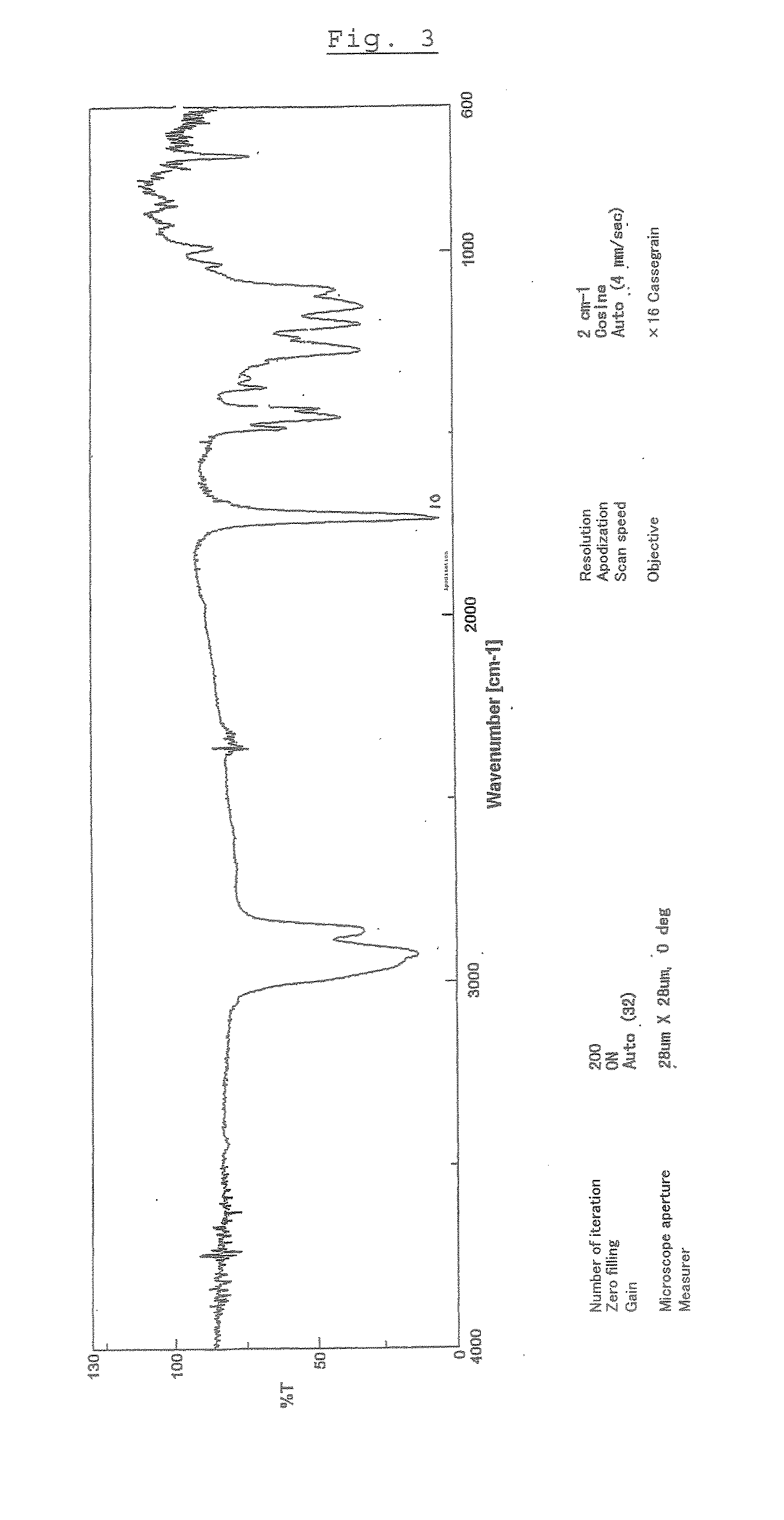
[0324]In 8.02 g of methylene chloride, a styrene / maleic anhydride copolymer (Dylark D232, 0.699 g) was dissolved, then 0.0438 g of aniline was added and they were stirred at room temperature for 1 hour. The reaction solution was introduced into methanol to perform solidification and precipitation to give the resin (P1). The resulting IR spectrum and 1H-NMR spectrum are shown in FIGS. 1 and 2.

polymer synthesis example 2

[0325]In a reaction vessel purged with nitrogen, 50 g of 8-methoxycarbonyl-8-methyltetracyclo[4.4.0.12,5.17,10]-3-dodecene represented by the above formula (Im), 2.3 g of 1-hexene as a molecular weight modifier and 100 g of toluene were placed, and they were heated to 80° C. Then, 0.09 ml of a toluene solution of triethylaluminum (0.6 mol / l) and 0.29 ml of a toluene solution of methanol-modified WCl6 (0.025 mol / l) were added, and reaction was performed at 80° C. for 3 hours to give the polymer. Subsequently, the resulting ring-opened copolymer solution was placed in an autoclave, and 100 g of toluene was further added. Then, RuHCl(CO)[P(CH5)]3 as a hydrogenation catalyst was added in an amount of 2500 ppm based on the amount of the monomers charged, and the hydrogen gas pressure was adjusted to 9 to 10 MPa, followed by reaction at 160 to 165° C. for 3 hours. After the reaction was completed, the reaction product was precipitated in a large amount of a methanol solution to give the h...

polymer synthesis example 3

[0326]In a reaction vessel purged with nitrogen, 20 g of 8-methoxycarbonyl-8-methyltetracyclo[4.4.0.12,5.17,10]-3-dodecene shown in Polymer Synthesis Example 2, 5.0 g of 5-methoxycarbonyl-5-methylbicyclo[2.2.1]hept-2-ene represented by the above formula (IIm), 1.2 g of 1-hexene as a molecular weight modifier and 86.3 ml of toluene were placed, and they were heated to 80° C. Then, 0.15 ml of a toluene solution of triethylaluminum (0.61 mol / l) and 0.47 ml of a toluene solution of methanol-modified WCl6 (0.025 mol / l) were added, and reaction was performed at 80° C. for 3 hours to give the polymer. Subsequently, the resulting ring-opened copolymer solution was placed in an autoclave, and 86.3 ml of toluene was further added. Then, RuHCl (CO)[P(C6H5)]3 as a hydrogenation catalyst was added in an amount of 2500 ppm based on the amount of the monomers charged, and the hydrogen gas pressure was adjusted to 9 to 10 MPa, followed by reaction at 160 to 165° C. for 3 hours. After the reaction w...


PUM

PropertyMeasurementUnit
wavelengthaaaaaaaaaa

Abstract

The present invention is intended to provide a thermoplastic resin composition which is inhibited from suffering phase separation and from which an optical film having excellent transparency is readily obtained, an optical film containing the composition as a main component, a retardation film which is a film obtained by stretching the optical film and exhibits positive wavelength dependence and has a small coefficient of photoelasticity and transparency, and a process for producing the retardation film. The thermoplastic resin composition contains (A) a cycloolefin-based polymer and (B) a vinyl-based polymer having a unit represented by the following formula (II):wherein at least one of R1 to R4 is a group represented by the formula (III), the remainder of R1 to R4 if any, and R5 and R6 are each a hydrogen atom, a halogen atom, a substituted) hydrocarbon group which may have a linkage containing a hetero atom, or a polar group, R5 and R6 may be bonded to each other to form a monocyclic or polycyclic group which may have a hetero atom, or may be united to form a divalent hydrocarbon group and Y is a divalent hydrocarbon group.

Description

TECHNICAL FIELD[0001]The present invention relates to a thermoplastic resin composition comprising a cycloolefin based resin and a vinyl-based polymer containing a structural unit having an amide group, an optical film containing the thermoplastic resin composition as a main component, and a process for producing the film. More particularly, the invention relates to an optical film which has excellent adhesion or bonding property to other materials, is highly transparent, gives retardation of high uniformity to a transmitted light and has properties that as the wavelength of a transmitted light becomes longer the absolute value of retardation becomes larger (also referred to as “positive wavelength dependence” hereinafter), and a process for producing the film.BACKGROUND ART[0002]Because films of polycarbonate, polyester, etc. which have been used as optical films in the past, have high coefficient of photoelasticity, a problem of change of retardation takes place. For example, chan...

Claims


Application Information

Patent Timeline
Patent Type & Authority Applications(United States)
IPC IPC(8): C08L45/00G02B1/04
CPCC08J5/18C08J2333/24C08J2365/00C08L33/24C08L35/06C08L45/00G02B5/3083C08L65/00C08L2666/04G02B5/30
Inventor MIYAKI, NOBUYUKIMIYAMOTO, YOSHIKAZUKAWASHIMA, NAOYUIKAJIWARA, ICHIROYOSHIDA, SOICHI
Owner JSR CORPORATIOON
Learn More