
Quartz glass body, method and casting mold for manufacturing same

a technology of quartz glass and casting molds, which is applied in the direction of glass making apparatus, glass growth process, glass shaping apparatus, etc., can solve the problems of inability to prevent or only hinder insignificant manner the uptake of water by the layer thickness of the separating agent, and the strength of this type of container suffers, so as to reduce the content of impurities, reduce the purity of the cast body, and simplify the manufacturing process

Inactive Publication Date: 2008-06-26
SCHOTT AG
View PDF11 Cites 43 Cited by
  • Summary
  • Abstract
  • Description
  • Claims
  • Application Information

AI Technical Summary

Benefits of technology

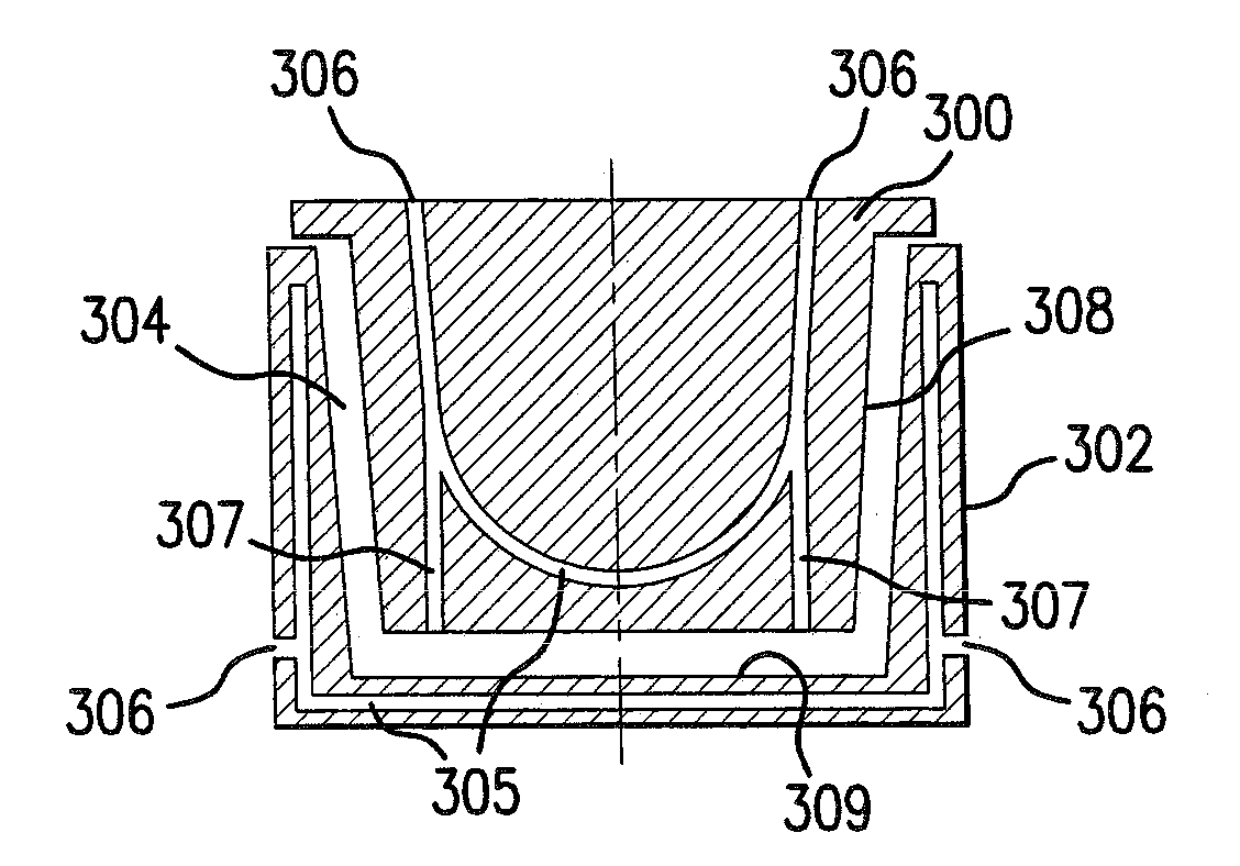
[0036]A further advantage of the invention relates to the purity of the cast body. While the purity (and / or impurities) in the bulk portion of the cast body is primarily currently determined by the purity of the raw material, the impurities in its surface region, i.e. within a surface layer of about 2 mm thick, strongly influence the casting process. Both together lead to an impurity content on the surface of clearly more than about 0.3 percent by weight for standard purity raw materials and clearly more than about 0.2 percent by weight for highly pure raw materials in the known manufacturing method. The content of impurities based only on the purity of the raw material is less than 0.2 percent by weight for the standard raw materials and less than 0.1 percent by weight for the highly pure raw material. This corresponds also to the values in the interior of the cast body. However that means that the impurities introduced by the casting process are significant and put limits on the purity of the cast body, even using very expensive highly pure raw materials.
[0037]The methods according to the present invention make it possible to considerably reduce the content of the impurities of the cast product that are caused by the casting process in contrast to the prior art. Cast bodies can be produced by the methods according to the present invention, which have impurity content in the surface region of less than 0.2 percent by weight and preferably less than 0.1 percent by weight. According to the quality of the raw material the impurities in the surface region can even be less than 0.07 percent by weight and with especially careful application of the methods of the invention even less than 0.04 percent by weight. The content of impurities in a surface layer of about 2 mm thick, which is removed, were analysed for their components.
[0038]The cladding is a matter of a smooth water-impermeable or watertight layer.
[0039]Cladding a gypsum mold with inserted or cut in watertight mats can provide shaping surfaces forming the water-impermeable surfaces. The casting mold can be clad with a preferably one-piece prefabricated mold, which is made from a water-impermeable substance, in another advantageous embodiment. For this purpose, prefabricated injection-molded molds made of plastic, particular made from silicone rubber or polyurethane (PU), are especially suitable.
[0040]According to an alternative embodiment the casting mold can be at least partially coated with a watertight or waterproof substance. This can occur by sealing, washing, and foam forming. Beeswax, for example, can provide a watertight coating, which must be applied so thick that the coating is watertight by closing the pores in the casting mold. Furthermore lacquer can be applied to the casting mold as the watertight coating. Both lacquer based on a plastic resin and lacquer with an acrylic base can be used for this purpose.
[0041]In another alternative embodiment of the method, which utilizes a casting mold with an outer part and an inner part, the latter inner part comprises a combustible material, which is later burned out in a sintering process. The combustible material can be a plastic material, such as Styropore or preferably polyurethane (PU) foam. Furthermore also natural materials, such as corn products, can be used. In this way manual removal of the core can be dispensed with, whereby the manufacturing process is simplified and made more economical. Furthermore inclined removal surfaces can be eliminated and inner contour can even be provided with an undercutting and less waste arises because of damage during removal.

Problems solved by technology

Problems always occur according to experience during removal of the green glass body from the gypsum mold, especially when a large-sized container is involved.
Another problem results because it is often desired to provide the container wall that comes in contact with the melted material with a fine-grained textured structure.
Because of that the strength of this sort of container suffers.
The layer thickness of the separating agent must not prevent or only hinder in an insignificant manner the uptake of water by the mold.
The disadvantage of this casting mold is that the slip must pass over a long flow path within the casting mold and this presupposes a corresponding high castability or pourability.
In that case a very long flow path and a corresponding non-uniform and asymmetrical filling of the mold results.
In contrast to that the case shown in FIG. 6B has the problem that a so-called flow front can result at the place where the individual material flows are combined.
At this place the bottom of the container that is produced can be inhomogeneous and especially susceptible to crack formation and breakage.
The problems resulting from the prior art methods include air inclusions, which occur when the material flows together (“flow front”), because the air cannot not escape and is included in the material.
Furthermore the container formed by the casting method must be put under a reduced load or reduced stress at the flow front location, which also can be caused by contamination of the slip mass by separating agent residues mixed with it.
As a result, there is a danger of crack formation because of the drying, which is especially great in the vicinity of material accumulations in the corners or in the bottom region of the container.

Method used


Image

  • Quartz glass body, method and casting mold for manufacturing same
  • Quartz glass body, method and casting mold for manufacturing same
  • Quartz glass body, method and casting mold for manufacturing same

Examples


Embodiment Construction

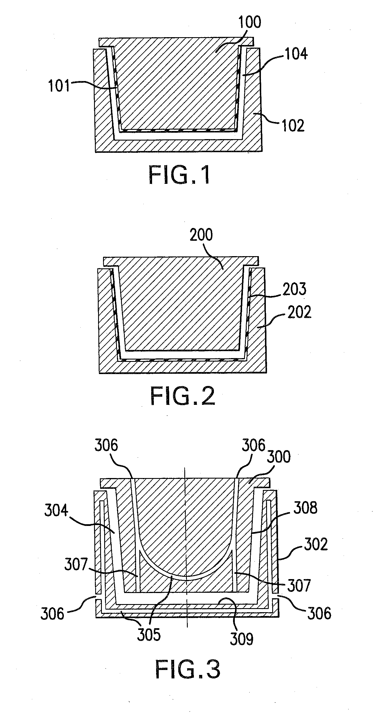
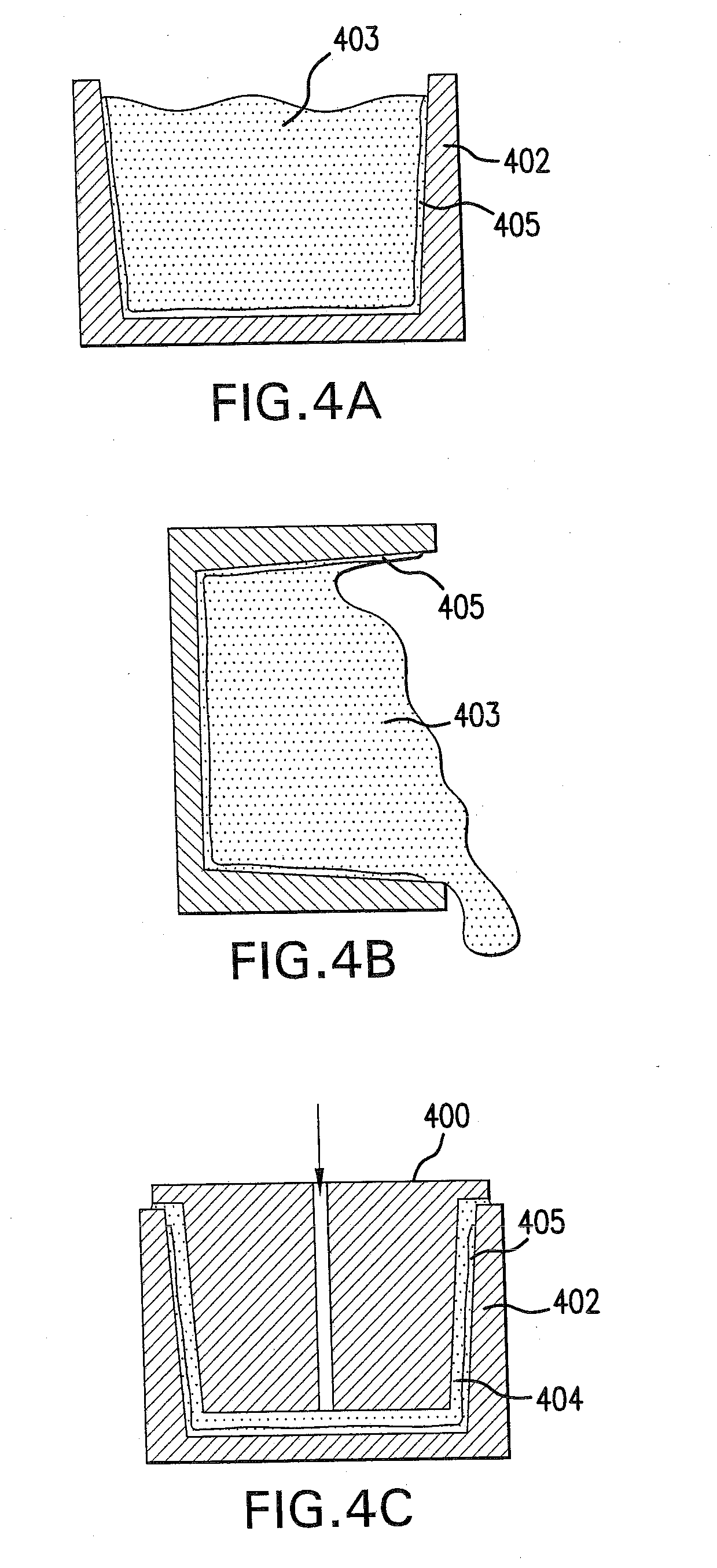
[0085]FIG. 1 is a schematic cross-sectional view through a casting mold according to the present invention. The casting mold comprises two parts, a core 100 and an outer part 102. The molding or shaping chamber 104 is between the core 100 and the outer part 102. The core 100 is clad or encased with a one-piece protective coating 101. The coating 101 comprises a watertight or water-impermeable material. It conforms to the shape of the core 100 and was prepared in this form, for example in an injection molding process. Silicone rubber is the preferred material for the coating 101. A silicone rubber coating with a thickness of 5 mm and a hardness of 60 Shore A has a sufficient strength for the present application.

[0086]The casting mold according to FIG. 2 is similarly shown in a cross-section view according to FIG. 2 and has a core 200 and an outer part 202. In this case the outer part 202 is coated with a pre-made cladding 203. The cladding 203 is made in one-piece and advantageously ...


PUM

PropertyMeasurementUnit
Timeaaaaaaaaaa
Timeaaaaaaaaaa
Percent by massaaaaaaaaaa

Abstract

The invention includes an improved quartz glass body, especially an improved quartz glass crucible for melting non-metals, non-ferrous metals, or silicon, and a method and casting mold for making it The quartz glass body is made by a method in which a quartz glass-water mixture is supplied to a casting mold comprising an outer part and an inner part, dried in the mold, and put under an overpressure during the drying. Later a resulting green glass body is removed from the mold. At least a portion of the shaping surfaces of the inner part of the mold are surfaces of a water-impermeable substance. The method provides a cast body with a reduced tendency to crack and with a smaller open porosity.

Description

CROSS-REFERENCE[0001]The invention described and claimed herein below is also described in German Patent Application 10 2006 060 561.6-45, filed on Dec. 21, 2006, in Germany, whose subject matter is hereby incorporated by reference thereto. This German Application provides the basis for a claim of priority under 35 U.S.C. 119 (a)-(d).BACKGROUND OF THE INVENTION[0002]1. The Field of the Invention[0003]The present invention relates to a method and casting mold for manufacture of a quartz glass body and to an improved quartz glass body, especially a container or crucible for melting non-metals or non-ferrous metals and especially for manufacture of a silicon ingot or block, from which photovoltaic modules are made.[0004]2. The Related Art[0005]Containers made of sintered quartz glass are predominantly used for making silicon blocks. These containers and / or molded parts and their manufacturing processes are disclosed, for example in DE 102 51 076 or DE 102 44 040. The containers are ess...

Claims


Application Information

Patent Timeline
IPC IPC(8): C03C3/06
CPCB28B1/16B28B1/265B28B23/0006C03B19/06H01L31/1804C03B20/00C03C3/06C30B11/002C30B35/002C03B19/066Y02P70/50C03B19/00C03B19/02
Inventor BORENS, MANFREDECKES, FRANZ-PETERZBOROWSKI, JANUSWESTERNHAGEN, KARSTEN V.MEROLLA, STEFANOWITTE, JOERGKUESTER, JOACHIMHOLLA, MARCUS
Owner SCHOTT AG
Learn More