
Magnesium alloy material and production process thereof

Active Publication Date: 2008-06-26
KOBE STEEL LTD +2
View PDF3 Cites 10 Cited by
  • Summary
  • Abstract
  • Description
  • Claims
  • Application Information

AI Technical Summary

Benefits of technology

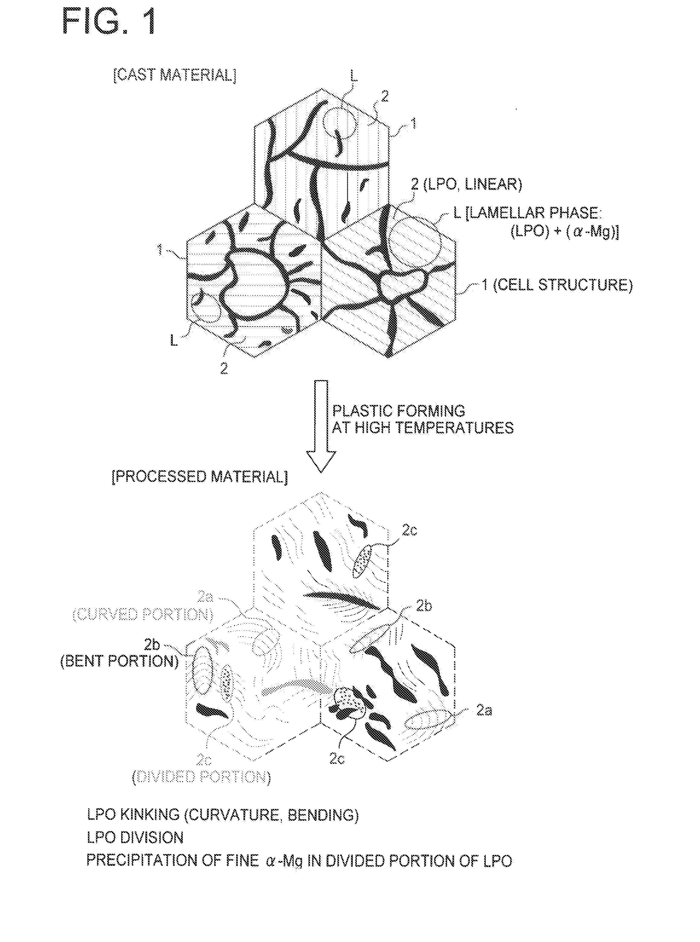
[0012]In this manner, mechanical properties (tensile strength, 0.2% yield strength and elongation) of the magnesium alloy material can be improved as a result of composing the magnesium alloy material from an Mg—Zn-RE alloy, having a lamellar layer formed from a long period stacking ordered structure and α-Mg in the alloy structure thereof, having at least one of a curved portion and a bent portion in at least a portion of the long period stacking ordered structure, and having a divided portion in the long period stacking ordered structure. Furthermore, since twin deformation of magnesium alloy crystals is prevented by the formation of a long period stacking ordered structure, the mechanical properties of the magnesium alloy material are improved. In addition, the long period stacking ordered structure is formed on the C-axis bottom surface of magnesium alloy crystals. Thus, the C-axis bottom surface becomes curved or bent as a result of making the long period stacking ordered structure curved or bent. Since such curvature or bending of the C-axis bottom surface makes it extremely difficult for dislocations to migrate during deformation, deformation of magnesium alloy crystals is prevented and mechanical properties of the magnesium alloy material are improved.
[0027]In addition, the process for producing a magnesium alloy material of the present invention allows a magnesium alloy material having improved mechanical properties as compared with conventional magnesium alloy materials to be efficiently produced using ordinary production equipment or processes.

Problems solved by technology

However, although the above-mentioned magnesium alloy materials allow the obtaining of high mechanical properties in specific production processes, these production processes have a disadvantage of requiring special equipment and having low productivity, while also having a problem of the existence of limitations on those members that can be used practically.

Method used


Image

  • Magnesium alloy material and production process thereof
  • Magnesium alloy material and production process thereof
  • Magnesium alloy material and production process thereof

Examples


examples

[0083]Examples of the present invention will be explained hereinafter.

examples 1 to 12

[0084]Mg—Zn-RE alloys having the compositions shown in Table 1 were placed in a melting furnace and dissolved by flux refining. Continuing, the heated and dissolved molten metal was cast in a metal mold to produce an ingot having an outer diameter of 29 mm and length of 60 mm. This ingot was subjected to an extruding process while changing the extrusion ratio so that the equivalent strain at an extrusion temperature of 375° C. was 0.7 to 2.2 to produce the magnesium alloy materials of Examples 1 to 12.

[0085]After polishing the surfaces of the resulting magnesium alloy materials of Examples 1 to 12 with #120 to #1000 sandpaper, the surfaces were mirrored by buffing with alumina and the like, after which the mirrored surfaces were etched with aqueous glycol acetate to prepare surfaces for observation of structure. These surfaces for observation of structure were observed with a light microscope at a magnification of 400× to observe the state of the long period stacking ordered (LPSO) ...

examples 13 to 20

[0089]Mg—Zn-RE alloys having the compositions shown in Table 2 were placed in a melting furnace and dissolved by flux refining. Continuing, the heated and dissolved molten metal was cast in a metal mold to produce an ingot having an outer diameter of 29 mm and length of 60 mm. This ingot was subjected to heat treatment for 2 hours at 510° C. followed by upset forging at a forging temperature of 350° C. while varying the upset ratio so that the equivalent strain from the direction orthogonal to the cylinder was 0.7 to 2.2 to produce the magnesium alloy materials of Examples 13 to 20.

[0090]The metal structures of the resulting magnesium alloy materials of Examples 13 to 20 were observed by light microscopy and TEM to confirm the state of the long period stacking ordered (LPSO) structure and the presence or absence of fine α-Mg having a mean particle diameter of 2 μm or less. In addition, JIS standard test pieces were cut out of the resulting magnesium alloy materials of Examples 13 to...


PUM

PropertyMeasurementUnit
Temperatureaaaaaaaaaa
Percent by atomaaaaaaaaaa

Abstract

The present invention provides a magnesium alloy material, having superior mechanical properties without using special production equipment or processes, and a production process thereof. The magnesium alloy material of the present invention composed of an Mg—Zn-RE alloy comprises essential components in the form of 0.5 to 3 atomic percent of Zn and 1 to 5 atomic percent of RE, with the remainder comprising Mg and unavoidable impurities. The Mg—Zn-RE alloy has a lamellar phase formed from a long period stacking ordered structure and α-Mg in the alloy structure thereof. The long period stacking ordered structure has at least one of a curved portion and a bent portion and has a divided portion in at least a portion thereof. Finely granulated α-Mg having a mean particle diameter of 2 μm or less is formed in the divided portion.

Description

BACKGROUND OF THE INVENTION[0001]1. Field of the Invention[0002]The present invention relates to a magnesium alloy material and a production process thereof, and more particularly, to a magnesium alloy material having high mechanical strength and a production process thereof.[0003]2. Description of the Related Art[0004]In general, since magnesium alloy materials have the lowest density and lightest weight among practically used alloys while also having high strength, they are being increasingly used in applications such as chassis of electrical products as well as automobile wheels, underbody parts and around-the-engine parts.[0005]Since parts used in automobile-related applications are particularly required to have high mechanical properties, materials of specific shapes are produced by a single roll process or rapid solidification process using magnesium alloy materials to which elements such as Gd or Zn have been added (see, for example, Japanese Patent Application Laid-open No. ...

Claims


Application Information

Patent Timeline
IPC IPC(8): C22C23/04
CPCC22C23/04C22F1/06C22C23/06
Inventor NAKATA, MAMORUYAMADA, YUUICHIITAKURA, KOJIOKADA, YOSHIOKAWAMURA, YOSHIHITOYAMASAKI, MICHIAKI
Owner KOBE STEEL LTD
Learn More