Cell structure of direct-flame fuel cell

a fuel cell and cell structure technology, applied in the field of direct-flame fuel cell cell structure, can solve the problems of reducing oxygen partial pressure and power generation efficiency, and power generation efficiency may be lowered, and achieve the effect of high power generation efficiency and low cos

Inactive Publication Date: 2008-06-19
SHINKO ELECTRIC IND CO LTD
View PDF0 Cites 1 Cited by
  • Summary
  • Abstract
  • Description
  • Claims
  • Application Information

AI Technical Summary

Benefits of technology

[0028]a circular green sheet of the solid electrolyte is worked into a conical shape in which an apex is located at the center, one surface is a concave surface, and the other surface is a convex surface. This makes it possible to manufacture a cell of a direct-flame fuel cell by an easy and low-cost method by working a circular green sheet of a solid electrolyte into a circular shape, shaping it into a conical shape, and firing the thus-shaped green sheet utilizing a conventional manufacturing process of a flat, circular cell as it is.
[0029]With the above configurations and methods, a cell of a direct-flame fuel cell can be realized in which a flame is prevented from going around to the cathode side or the degree in which a flame goes around to the cathode side is low and which is hence high in power generation efficiency.

Problems solved by technology

However, in the entirely flat cell having the flat-plate-like solid electrolyte layer 10, when a flame 16 is applied to the anode-layer-12-side surface, the flame 16 tends to go around from the anode layer 12 side to the cathode layer 14 side as indicated by arrows A. The flame 16 going around to the cathode layer 14 side raises a problem that the power generation efficiency may be lowered due to reduction in oxygen partial pressure on the cathode layer 14 side.[Patent document 1] JP-A-2004-139936[Patent document 2] JP-A-2005-353571[Patent document 3] JP-A-2006-190592
As described above, the cell of the conventional direct-flame fuel cell in which the anode layer and the cathode layer are formed on the entirely flat solid electrolyte layer is associated with the problem that when a flame is applied to the anode layer of the cell, the flame goes around to the cathode layer side and thereby causes reduction in oxygen partial pressure and power generation efficiency.

Method used


Image

  • Cell structure of direct-flame fuel cell
  • Cell structure of direct-flame fuel cell
  • Cell structure of direct-flame fuel cell

Examples


Embodiment Construction

[0036]An embodiment of the present invention will be hereinafter described in detail with reference to the accompanying drawings.

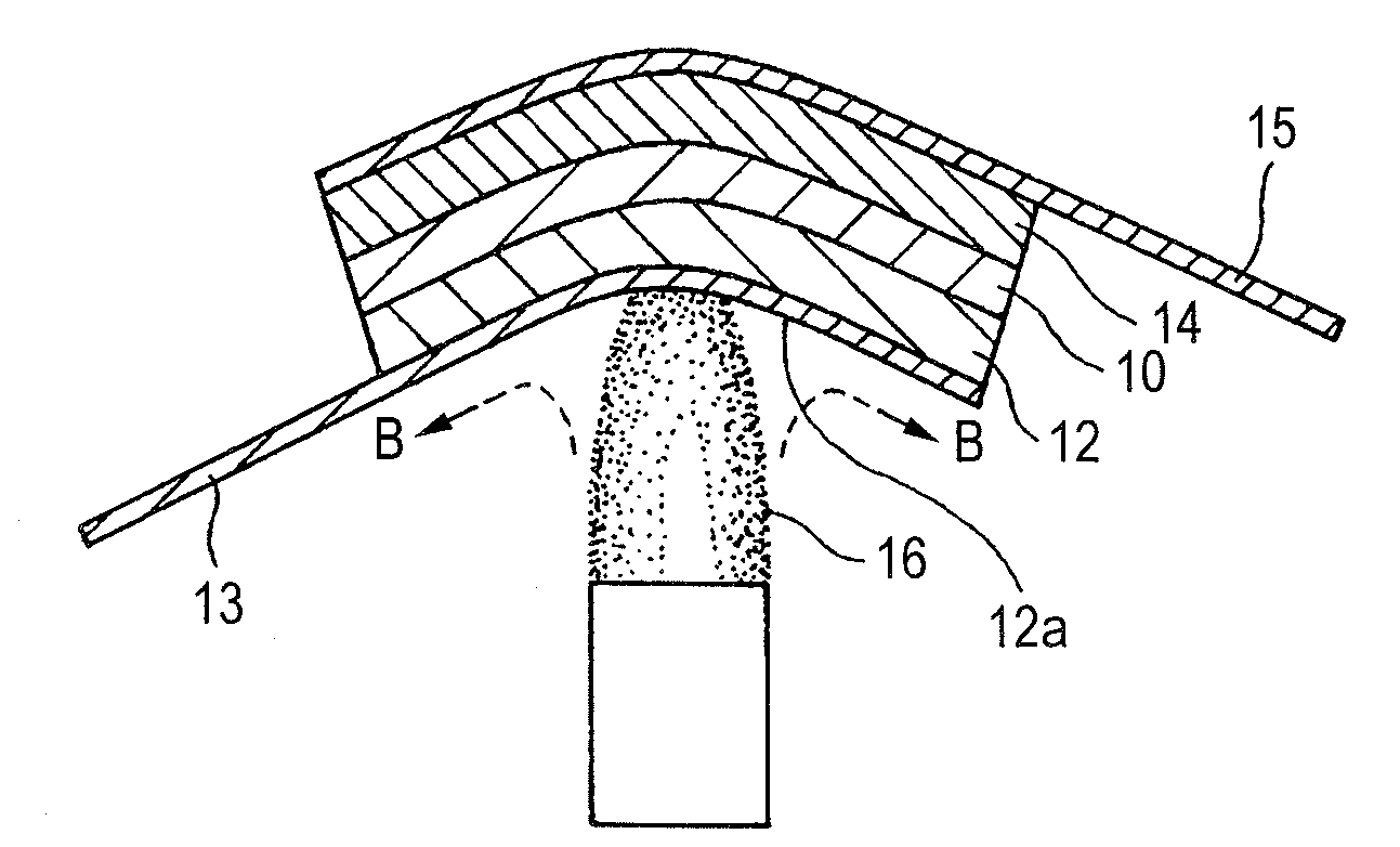
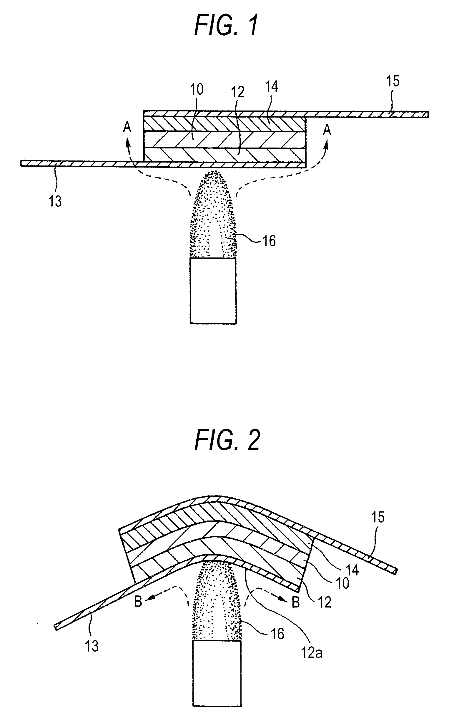
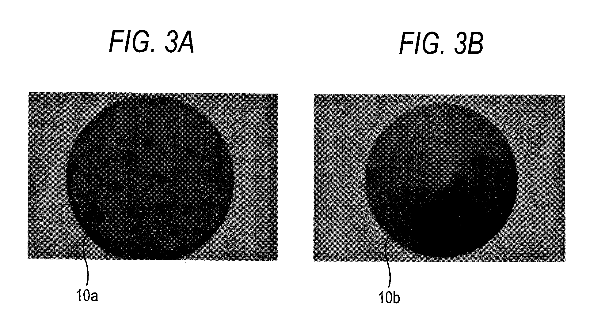
[0037]FIG. 2 is for description of the configuration of a cell of a direct-flame fuel cell according to a first embodiment of the invention as well as its manufacturing method. FIGS. 3A and 3B show shapes of a green sheet of a solid electrolyte before firing which is used to manufacture a cell.

[0038]As shown in FIG. 2, the configuration of the cell of the direct-flame fuel cell according to the invention is the same as the conventional cell in that an anode layer 12 is formed on one surface of a solid electrolyte layer 10 and a cathode layer 14 is formed on the other surface and electrodes 13 and 15 are connected to the anode layer 12 and the cathode layer 14, respectively. However, in the invention, the cell is curved so that the anode layer 12 side assumes a concave shape and the cathode layer 14 side assumes a convex shape. Oxygen or an oxygen-containin...


PUM

PropertyMeasurementUnit
angleaaaaaaaaaa
angleaaaaaaaaaa
diameteraaaaaaaaaa

Abstract

A cell of a solid electrolyte direct-flame fuel cell generates power in a state that the cell is placed inside or in the vicinity of a flame (16). The cell is configured in such a manner that a cathode layer (14) is formed on one surface of a solid electrolyte layer (10) and an anode layer (12) is formed on the other surface. The cell is characterized by being curved so that the anode layer side has a concave shape and the cathode layer side has a convex shape.

Description

BACKGROUND OF THE INVENTION[0001]The present invention relates to a cell structure of a direct-flame fuel cell. In particular, the invention relates to a cell structure of a direct-flame fuel cell which generates power by placing the cell of a solid electrolyte fuel cell inside or in the vicinity of a flame and thereby keeping the temperature of the cell at its operating temperature utilizing the heat of the flame.[0002]Fuel cells have been developed and put in practical use as low-pollution power generating means to replace thermal power generation etc. and electric energy sources of electric cars to replace engines that use gasoline etc. as fuels. And many studies have been made to increase the efficiency and reduce the cost of fuel cells.[0003]Fuel cells employ various kinds of power generation methods, and fuel cells which use a solid electrolyte are known as one type. Among the fuel cells using a solid electrolyte is one which uses, as an oxygen ion conduction type solid electr...

Claims


Application Information

Patent Timeline
Patent Type & Authority Applications(United States)
IPC IPC(8): H01M8/10B05D5/12
CPCH01M8/002H01M8/04022H01M8/04089Y02E60/525H01M8/1206H01M8/122Y02E60/521H01M8/0612H01M8/1231Y02E60/50
Inventor YOSHIIKE, JUNSUGANUMA, SHIGEAKIKATAGIRI, FUMIMASATOKUTAKE, YASUE
Owner SHINKO ELECTRIC IND CO LTD
Why Eureka
Try Eureka