Method for manufacturing light guide plate stamper

a technology of light guide plate and stamper, which is applied in the direction of photosensitive material processing, photomechanical equipment, instruments, etc., can solve the problems of high cost, high manufacturing time, and the above-described method of producing an injection molding mold with certain problems, and achieves high precision, low cost, and easy production.

Inactive Publication Date: 2005-02-10
HON HAI PRECISION IND CO LTD
View PDF4 Cites 15 Cited by
  • Summary
  • Abstract
  • Description
  • Claims
  • Application Information

AI Technical Summary

Benefits of technology

[0009] An object of the present invention is to provide a relatively easy, low-cost method for manufacturing an LGP stamper that has highly precise micro patterns formed thereon.

Problems solved by technology

However, the above-described method for producing an injection molding mold has certain problems.
In particular, a precision of the reverse micro patterns on the mold is generally not satisfactory, because these patterns are easily damaged when the silver film is stripped off or when the residual silver film is removed.
In addition, said method is somewhat complicated, resulting in much manufacturing time being spent and correspondingly high costs.

Method used


Image

  • Method for manufacturing light guide plate stamper
  • Method for manufacturing light guide plate stamper
  • Method for manufacturing light guide plate stamper

Examples


Embodiment Construction

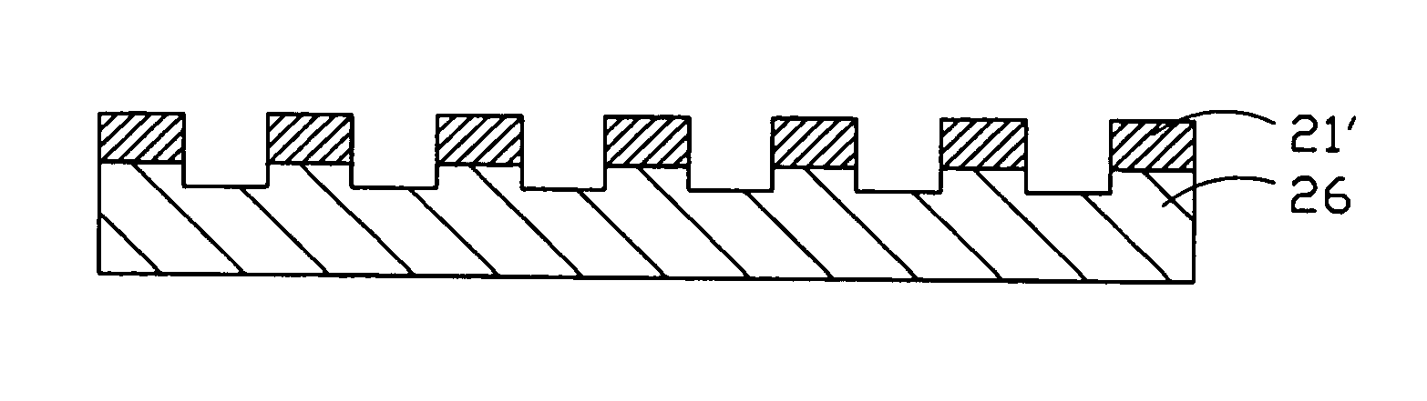
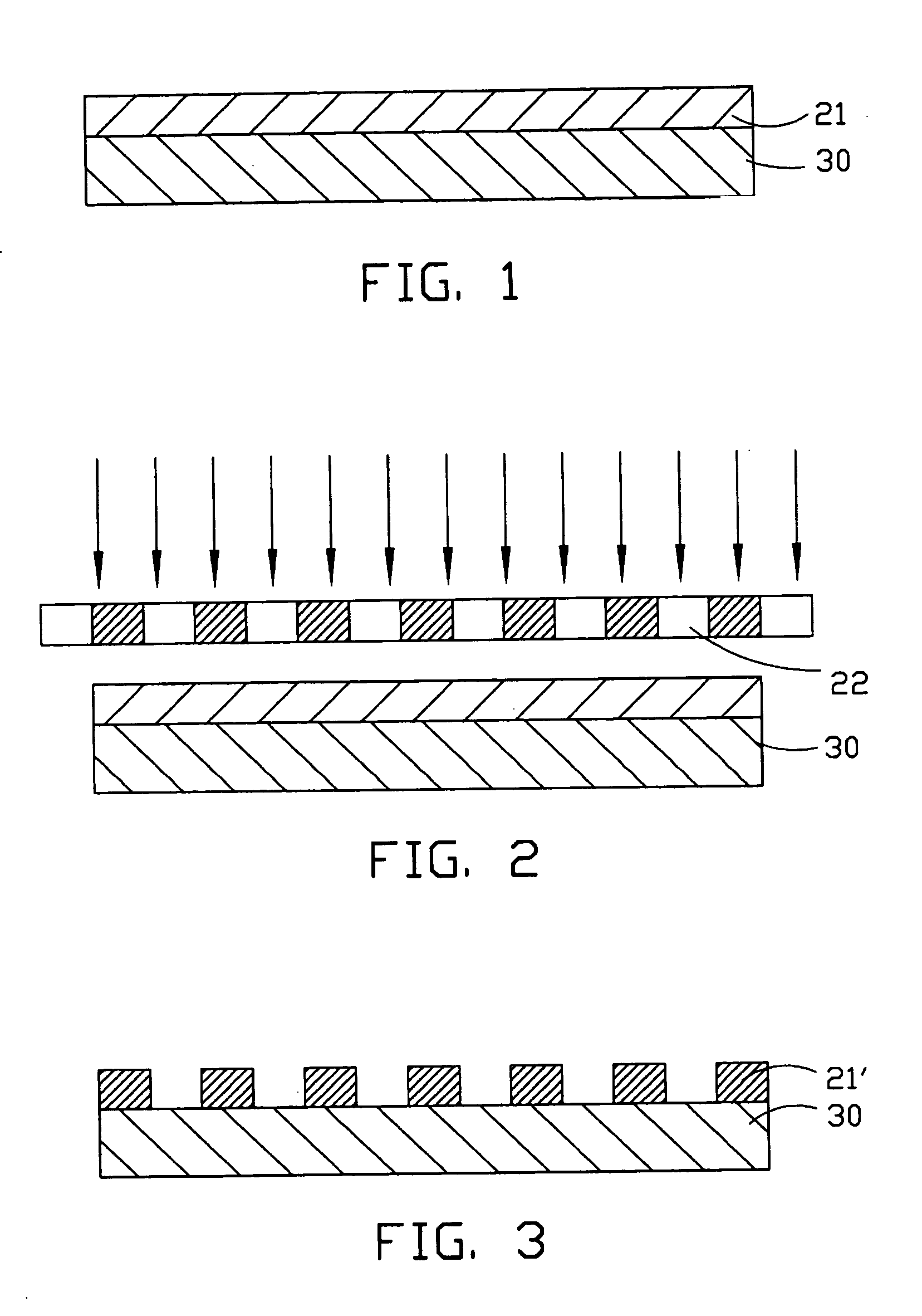
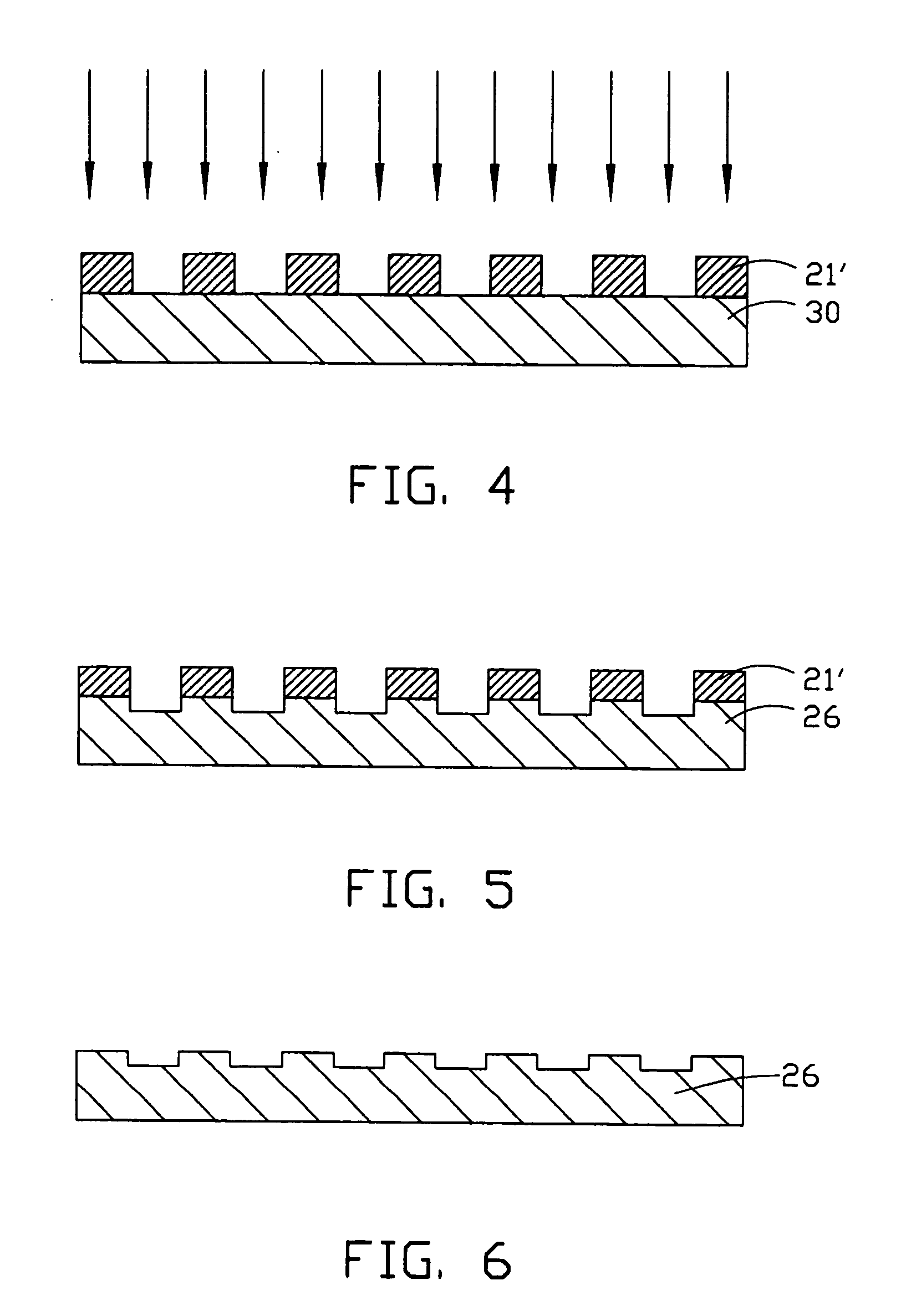
[0013] FIGS. 1 to 6 show processing steps of a preferred embodiment of a method for manufacturing an LGP stamper. Referring to these figures, said manufacturing method includes the following steps: [0014] Preparing a metal, alloy or silicon wafer substrate 30, and forming a photo-resist film 21 on the substrate 30; exposing and developing the photo-resist film 21 utilizing a photo-mask 22 to form micro patterns 21′; etching the substrate 30 by means of a dry etching method to form a preform including a stamper 26; and stripping off or otherwise removing residual patterns 21′ from the substrate 30 to form the LGP stamper 26.

[0015] The method is described in more detail below: [0016] (1) Preparing the metal or alloy substrate 30, and forming the photo-resist film 21 on the substrate 30, as shown in FIG. 1. First, the substrate 30 is placed in a coating machine, and the photo-resist film 21 is coated on the substrate 30 to a thickness of about 20 microns. This is performed at a speed ...


PUM

PropertyMeasurementUnit
thicknessaaaaaaaaaa
thicknessaaaaaaaaaa
adhesionaaaaaaaaaa

Abstract

A method for manufacturing a light guide plate (LGP) stamper (26) includes the steps of: forming a photo-resist film (21) on a substrate (30); exposing and developing the photo-resist film to form micro patterns (21′); etching the substrate by means of a dry etching method to form a perform including the stamper; and stripping off residual patterns from the substrate to form the LGP stamper.

Description

BACKGROUND OF THE INVENTION [0001] 1. Field of the Invention [0002] This invention generally relates to a method for manufacturing a stamper, and particularly relates to a method for manufacturing a stamper used for manufacturing a light guide plate (LGP) of a backlight module. [0003] 2. Prior Art [0004] In recent years, implementation of word processors in compact personal computers has boomed, and portable personal computers known as laptops and notebooks are now in widespread use. In such portable personal computers, a liquid crystal display (LCD) device is commonly used as the display unit. [0005] Conventionally, a backlight module is disposed at a rear side of an LCD screen for lighting the whole LCD screen. To achieve a display with high clarity and resolution, the backlight module providing illumination for the LCD device is required to emit light with high luminance and uniformity. The LGP of the backlight module is key to providing the needed luminance and uniformity. More ...

Claims


Application Information

Patent Timeline
Patent Type & Authority Applications(United States)
IPC IPC(8): F21V8/00G03F7/00G03F7/36
CPCG02B6/0036G03F7/0017G02B6/0065
Inventor CHEN, GA-LANETSAI, KUN-JUNGYU, TAI-CHERNG
Owner HON HAI PRECISION IND CO LTD
Why Eureka
Try Eureka