
Method of joining tantalum clade steel structures

a technology of clade steel and clade, which is applied in the direction of manufacturing tools, welding/soldering/cutting articles, transportation and packaging, etc., can solve the problems of high cost of the basic tantalum clad steel section, difficult and expensive fabrication, and brittle and non-corrosion resistant phases in the tantalum

Inactive Publication Date: 2008-06-19
GLAS TRUST +1
View PDF99 Cites 53 Cited by
  • Summary
  • Abstract
  • Description
  • Claims
  • Application Information

AI Technical Summary

Benefits of technology

"The invention provides a low cost, chemical resistant, and material and manpower efficient way to join tantalum sheets together in a way that prevents interaction with the process fluid. This is important because tantalum is a highly expensive material and many techniques have high costs or cause damage to the tantalum. The invention uses cold spray, a process that employs a high velocity gas jet to rapidly accelerate powder particles to high velocity, to create an impermeable piece without heating the tantalum powder to a temperature near or above its melting point. This process is efficient and has advantages over traditional thermal spray. The invention also provides a solution for joining tantalum clad to steel or stainless steel, which is difficult and expensive. Overall, the invention provides a cost-effective and efficient way to join tantalum sheets for various industrial applications."

Problems solved by technology

Because tantalum is very expensive often the structural components used in this equipment are made up of a steel or stainless steel section for strength purposes that is clad with a thin sheet of tantalum to prevent interaction with the process fluid.
Many techniques have been used but all of them are costly, have severe deficiencies, and cause the cost of the basic tantalum clad steel section to be higher than necessary.
This is critical because at elevated temperatures, such as in a molten Ta weld pool, Ta can dissolve the elemental components of steels and stainless steels with the result that brittle and non corrosion resistant phases form in the tantalum.
The fabrication problem becomes difficult and expensive however when the individually clad components must be joined together to form a fully functional vessel such as a process reactor.
Dissolution of the steel into the tantalum during either fusion process would immediately destroy the desirable properties of tantalum.
The problems become far more difficult when welding rings to rings to form long vessels, or domes to rings to provide a pressure closure or even vessel penetrations for piping.
Bending the tantalum sheet in a circular pattern, then bending 90 degrees out of the plane of the circle, inserting the batten and bending the two tantalum sheets flat again is time consuming and difficult.
Because these joints are used on large structures they usually must be made in air, thus the hot plasma arc causes both the tantalum sheet and the tantalum powder to oxidize due to the plasma's very high temperature.
The porosity and porous grain boundaries greatly reduce the corrosion resistance by percolation effects and the high oxygen content results in a less ductile (than the tantalum sheet) deposit that is prone to cracking and can fail during operation.
Additionally, because the coating is put down hot, and because the coefficient of thermal expansion for tantalum is almost double that of steel, as the structure cools the brittle plasma spray deposit is put in a state of tensile stress, a stress that potentially can lead to cracking and failure of the coating.
However, the method is severely limited in that at least one of the articles must be a spray formed steel article and the sprayed particles must be steel particles.

Method used


Image

  • Method of joining tantalum clade steel structures
  • Method of joining tantalum clade steel structures
  • Method of joining tantalum clade steel structures

Examples


Embodiment Construction

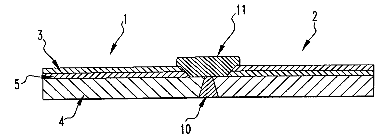
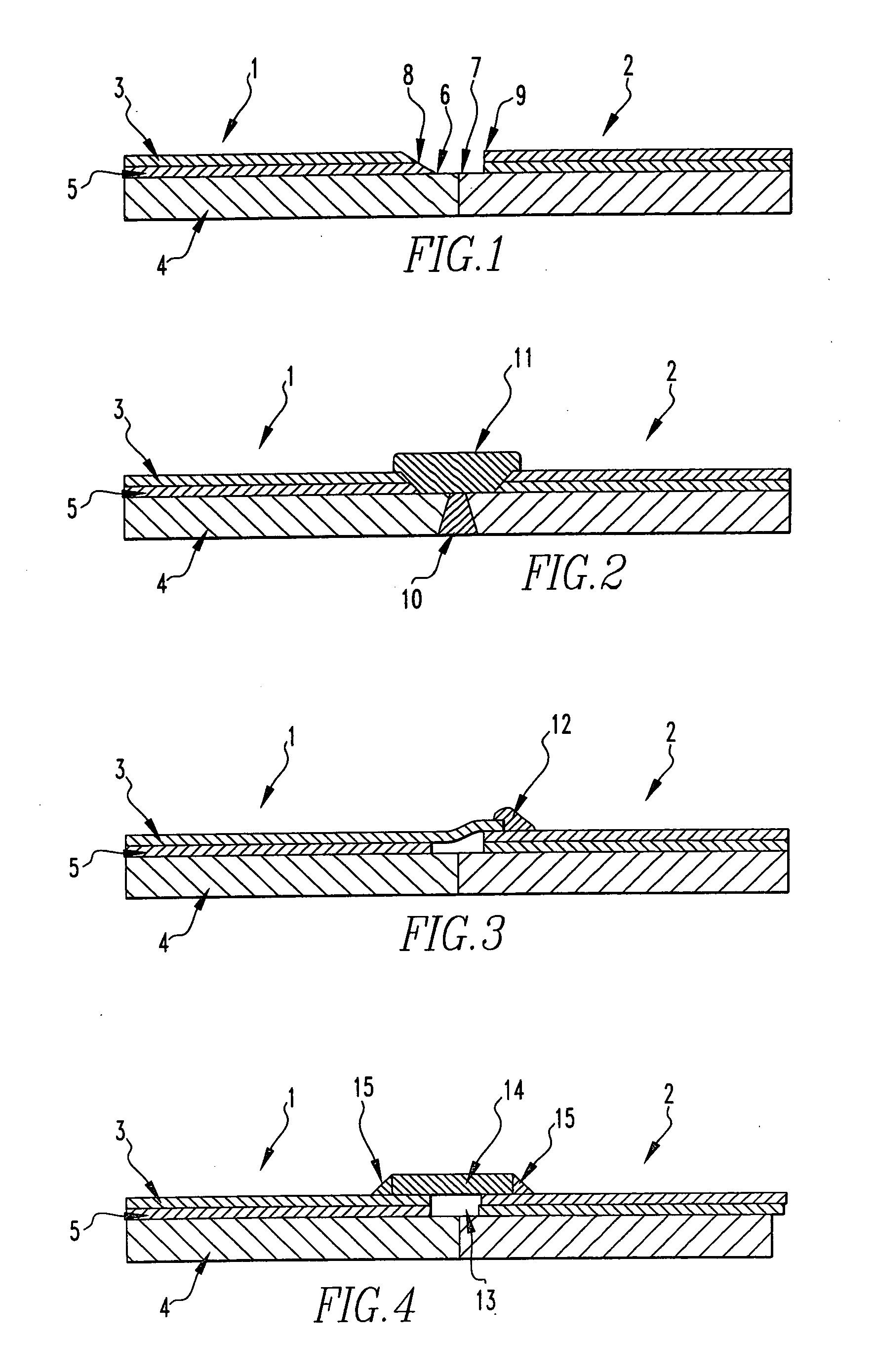
[0017]The present invention is broadly directed to a process for joining tantalum clad steel structures comprising:[0018]a) providing a first tantalum clad section, said first tantalum clad section comprising a tantalum layer over a steel layer, with a bonding layer optionally therebetween, with a portion of said steel layer in an edge region not being covered by said tantalum layer or said bonding layer,[0019]b) providing a second tantalum clad section, said second tantalum clad section comprising a tantalum layer over a steel layer, with a bonding layer optionally therebetween, with a portion of said steel layer in an edge region not being covered by said tantalum layer or said bonding layer,[0020]c) locating said steel edge regions adjacent each other,[0021]d) welding the steel edge regions together,[0022]e) cold spraying a tantalum powder onto the welded edge regions and over the tantalum layers adjacent said edge regions thereby joining the tantalum clad steel sections.

[0023]Th...


PUM

PropertyMeasurementUnit
thicknessesaaaaaaaaaa

Abstract

The present invention is directed to a process for joining tantalum clad steel structures. The process broadly comprises:a) providing a first tantalum clad section, said first tantalum clad section comprising a tantalum layer over a steel layer, with a bonding layer optionally therebetween, with a portion of said steel layer in an edge region not being covered by said tantalum layer or said bonding layer,b) providing a second tantalum clad section, said second tantalum clad section comprising a tantalum layer over a steel layer, with a bonding layer optionally therebetween, with a portion of said steel layer in an edge region not being covered by said tantalum layer or said bonding layer,c) locating said steel edge regions adjacent each other,d) welding the steel edge regions together,e) cold spraying a tantalum powder onto the welded edge regions and over the tantalum layers adjacent said edge regions thereby joining the tantalum clad steel sections.The invention is also directed to tantalum welds or joints formed by cold spraying tantalum powder.

Description

BACKGROUND OF THE INVENTION[0001]Tantalum is a highly corrosion resistant, bio-friendly metal. As a result it finds wide use in reactors, heat exchangers, piping and the like in the chemical and pharmaceutical processing industries. Because tantalum is very expensive often the structural components used in this equipment are made up of a steel or stainless steel section for strength purposes that is clad with a thin sheet of tantalum to prevent interaction with the process fluid. In order for the tantalum sheet to provide corrosion protection for a whole vessel many such sheets must be joined together into a single impermeable piece. Many techniques have been used but all of them are costly, have severe deficiencies, and cause the cost of the basic tantalum clad steel section to be higher than necessary. This invention provides a low cost, chemical resistant, material and manpower efficient means of joining the tantalum sheets together.[0002]Cold spray or kinetic spray (see U.S. Pat...

Claims


Application Information

Patent Timeline
Patent Type & Authority Applications(United States)
IPC IPC(8): B32B15/00B23K28/00
CPCB23K31/02B23K2201/18B23K2201/34B23K2203/04Y10T428/12347C23C24/04B32B38/08Y10T428/12076B23K2203/16B23K2103/05B23K2103/166B23K2101/18B23K2101/34B23K2103/04B23K2103/16
Inventor MILLER, STEVEN A.SHEKHTER, LEONID N.ZIMMERMAN, STEFAN
Owner GLAS TRUST
Learn More