Phase-locked loop circuit, delay locked loop circuit, timing generator, semiconductor test instrument, and semiconductor integrated circuit
a phase lock and loop circuit technology, applied in pulse manipulation, pulse technique, instruments, etc., can solve the problems of poor linearity of vco voltage (or delay voltage), large power consumption, and deterioration of phase lock accuracy, so as to improve practical accuracy, reduce errors, and improve reliability
- Summary
- Abstract
- Description
- Claims
- Application Information
AI Technical Summary
Benefits of technology
Problems solved by technology
Method used
Image
Examples
first embodiment
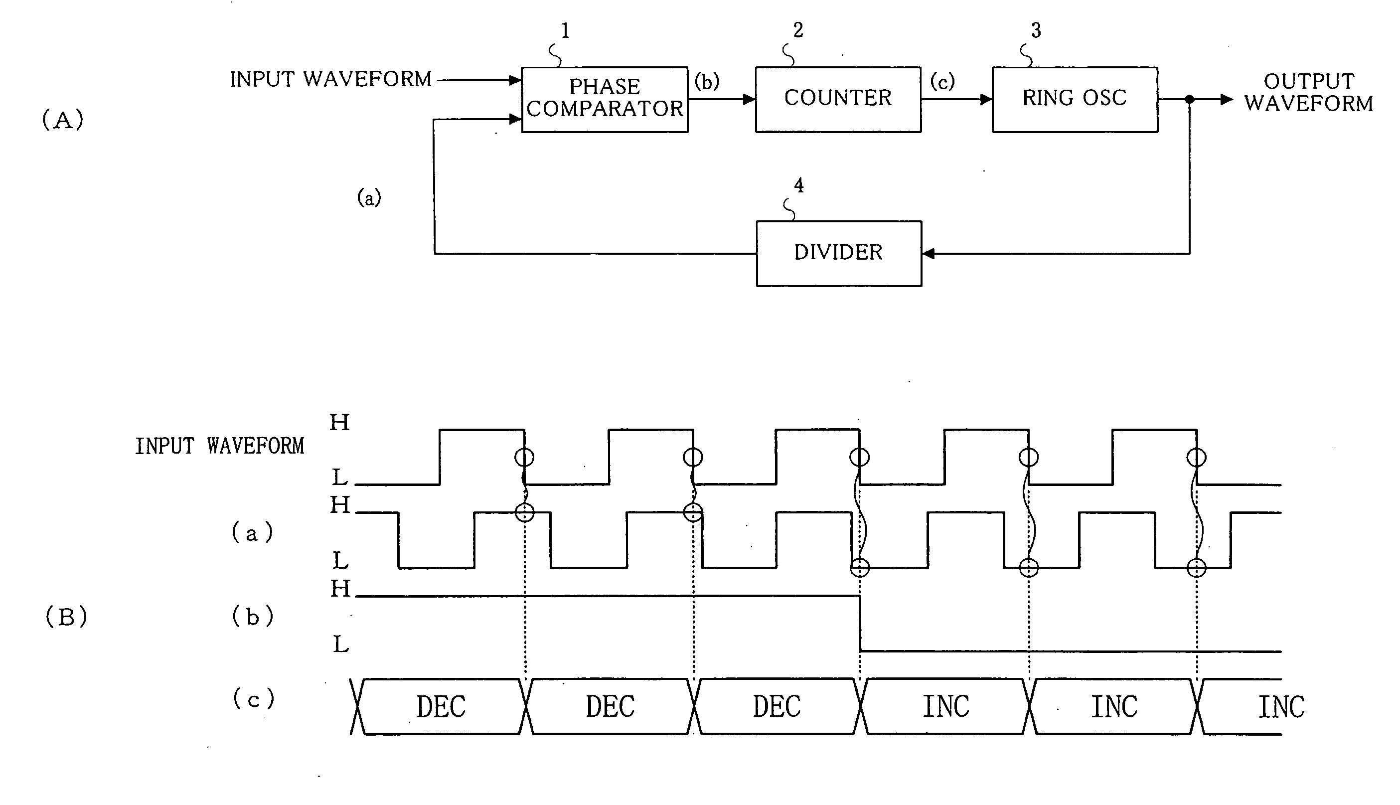
[0093]First, an example of a phase-locked loop circuit (PLL) according to the present invention will be described as a first embodiment.
[0094]As shown in FIG. 1(A), a PLL according to the first embodiment comprises a phase comparator 1, a counter 2, a ring oscillator (RING OSC) 3, and a frequency divider 4. Further, in the PLL, an output signal (output waveform) as a binary signal of the ring oscillator 3 is divided by the frequency divider 4, and inputted to the phase comparator 1 as a feedback signal as a binary signal which is “H” or “L”.
[0095]To the phase comparator 1 is inputted an input signal (input waveform) together with the feedback signal. Then, the phase comparator 1 detects a value of the feedback signal in synchronization with the input signal. In this embodiment, as shown in FIG. 1(B), the phase comparator 1 samples a value of the feedback signal with a timing of a trailing edge of the input signal.
[0096]Subsequently, the phase comparator 1 outputs a detection result ...
second embodiment
[0130]Another example of the PLL according to the present invention will now be described as a second embodiment with reference to FIG. 5.
[0131]In the second embodiment, respective constituent components other than the ring oscillator 3 are the same as those in the above-described first embodiment, thereby eliminating their explanation.
[0132]The ring oscillator 3 according to the second embodiment comprises inverters 30 connected in series on multiple stages like the first embodiment. Moreover, it comprises variable capacitances 32 provided between the respective inverters 30 and a grounded voltage source.
[0133]Additionally, the respective variable capacitances 32 comprise load capacitances 322 whose number is equal to the number of bits in the control signal and which are connected with each other in parallel, and switching elements 321 which are connected with the respective load capacitances 322 in series.
[0134]Here, a gate capacitance of the transistor is utilized as the load ca...
third embodiment
[0137]Still another example of the PLL according to the present invention will now be described as a third embodiment.
[0138]Like the above-described first and second embodiments, the digital-controlled PLL can reduce a cycle clock number required until feedback is applied after passing a lock target as compared with a conventional analog-controlled PLL. As a result, a loop lock band can be increased.
[0139]Meanwhile, in a D flip-flop such as shown in FIG. 6(A), a phase difference when an output value is switched from “H” to “L” from a timing to detect a division signal such as shown in FIG. 6(B) may not be necessarily equal to a phase difference when the output value is switched from “L” to “H” in some cases.
[0140]In such a case, as shown in FIG. 6(C), there may be generated hysteresis that a phase difference between a feedback signal such as a data signal and an input signal such as a clock signal differs depending on a change direction of an output value of the D flip-flop. In part...
PUM
 Abstract
Description
Claims
Application Information
 - R&D
- Intellectual Property
- Life Sciences
- Materials
- Tech Scout
- Unparalleled Data Quality
- Higher Quality Content
- 60% Fewer Hallucinations
Browse by: Latest US Patents, China's latest patents, Technical Efficacy Thesaurus, Application Domain, Technology Topic, Popular Technical Reports.
© 2025 PatSnap. All rights reserved.Legal|Privacy policy|Modern Slavery Act Transparency Statement|Sitemap|About US| Contact US: help@patsnap.com


