
Methods and systems of producing fuel for an internal combustion engine using a plasma system at various pressures

a technology of plasma system and fuel, which is applied in the direction of machines/engines, bulk chemical production, separation processes, etc., can solve the problem of not making steam reforming of hydrocarbons amenabl

Inactive Publication Date: 2008-06-05
TETROS INNOVATIONS LLC
View PDF49 Cites 10 Cited by
  • Summary
  • Abstract
  • Description
  • Claims
  • Application Information

AI Technical Summary

Benefits of technology

[0009]Systems and methods for producing fuel from a

Problems solved by technology

The processing equipment needed and / or the time for heating of the reactor to generate a temperature sufficient to generate molecular hydrogen using a steam methane reforming process does not make steam reforming of hydrocarbons amenable for rapid-start, compact, portable applications (for example, automobiles and / or buses).

Method used


Image

  • Methods and systems of producing fuel for an internal combustion engine using a plasma system at various pressures
  • Methods and systems of producing fuel for an internal combustion engine using a plasma system at various pressures
  • Methods and systems of producing fuel for an internal combustion engine using a plasma system at various pressures

Examples


example

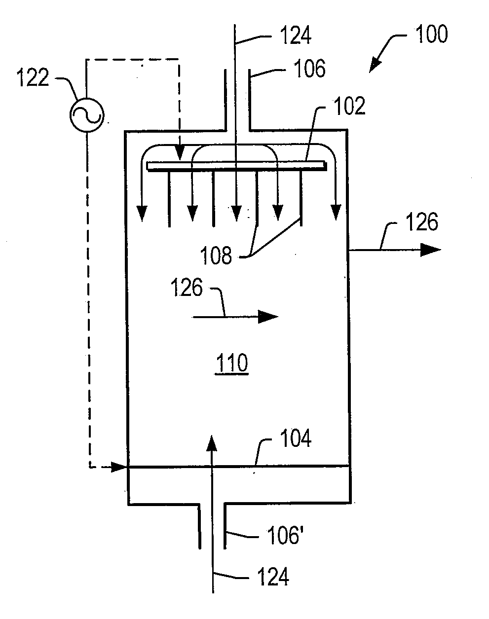
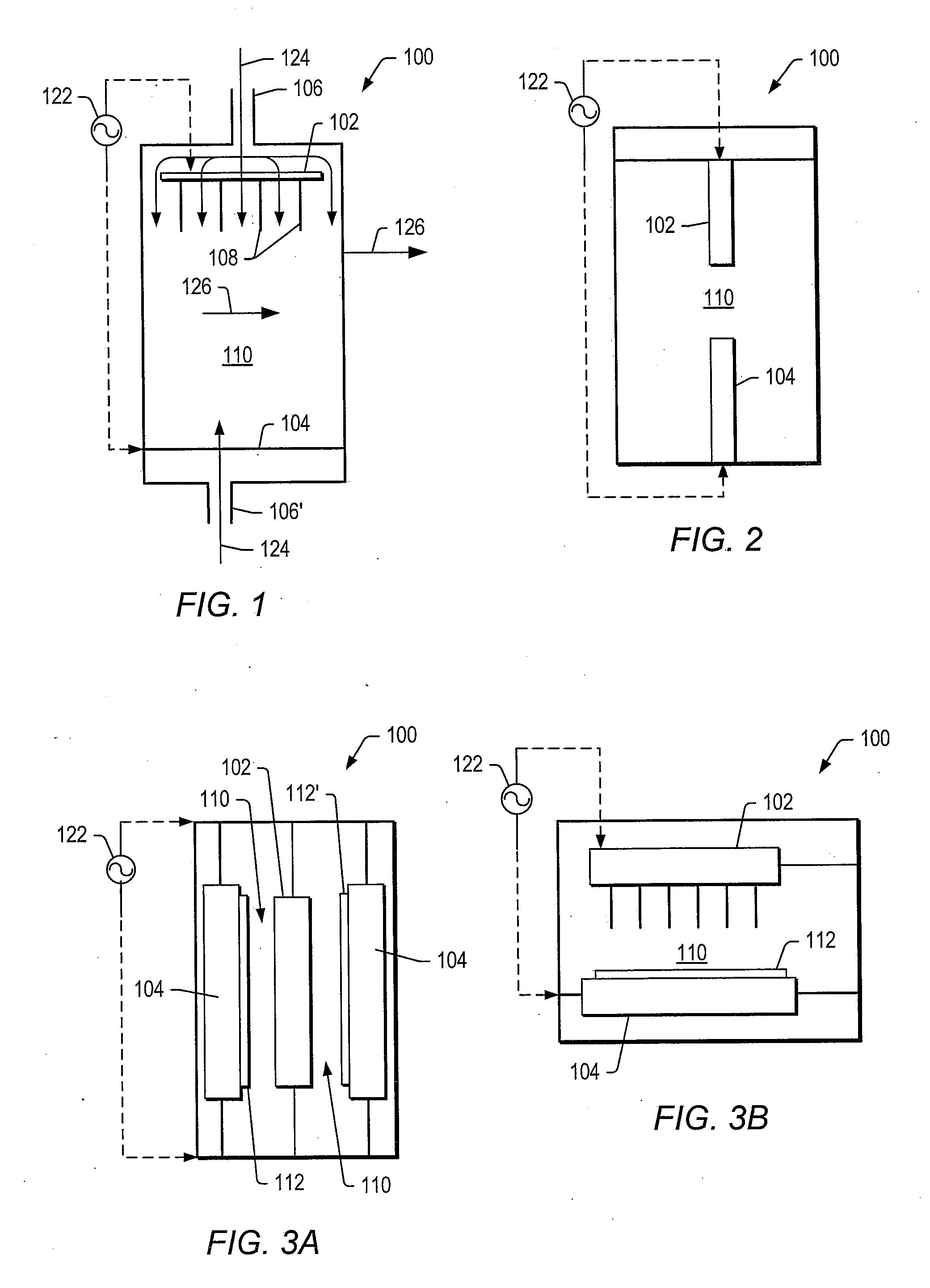
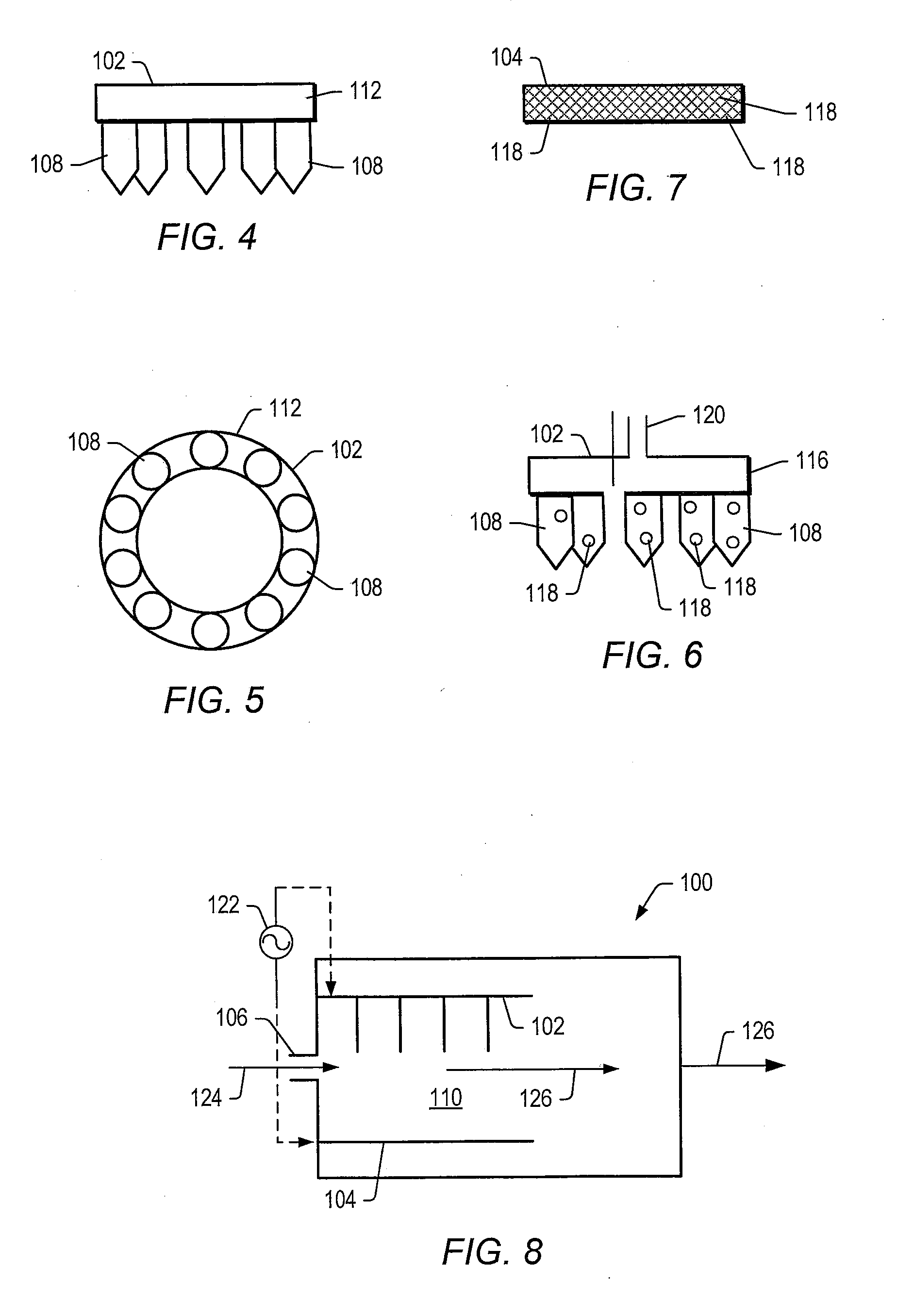
[0102]A tubular reactor was equipped with two vertically oriented electrodes with a ½ inch quartz tube (plasma generating zone) positioned between the electrodes. The cathode electrode (¼″ stainless steel tube) was positioned at the bottom of the tubular reactor. The cathode electrode included an opening to allow generated gas to leave the reactor. The anode electrodes (10 1 / 16″ inch stainless steel needles) were positioned at the top of the tubular reactor. The anode electrodes were connected to a pump that delivered aqueous ethanol into the plasma-generating zone. Anode electrodes were connected to a high voltage amplifier (Trek 20 / 20C) equipped with a pulse signal input (HP), and the cathode electrode was grounded. The gap between the anode and cathode electrodes was 15 mm. Temperature of the plasma in the gap was estimated to be between 260° C. and 280 ° C. using an IR digital temperature probe.

[0103]Catalysts listed in TABLE 1 were positioned next to the plasma zone. In certain...

example 2

[0107]The plasma reformer as described in Example 1 without catalyst was run at 5 psig and 10 psig. The results of at experimental conditions, various pressures, and products formed are listed in TABLE 3.

TABLE 3Experiment condition5 psig10 psigH2O / EtOH ratio3.243.24Feed rate (mmol / min)1.151.00Voltage RMS (kV)4.054.66Current RMS (mA)2.202.17Frequency (kHz)6.546.20Power RMS (W)2.973.51SummaryH2 + CO Productivity (sccm)139.2131.4H2 selectivity111% 120% CO selectivity82%87%CO2 selectivity 7% 7%HC selectivity11% 6%Reformer efficiency79%82%

Selectivity of COx=mole of product COx / (2×mole of converted ethanol)×100.

Selectivity of H2=mole of product H2 / (3×mole of converted ethanol)×100.

Converted ethanol was the total number of moles of ethanol in the following reactions:

C2H5OH+H20=2CO+4H2

C2H5OH+H2=2CH4+H2O

C2H5OH=C2Hx+H2O+yH2,

which was back calculated fro mole products CO, C2Hx and CH4. CO, C2Hx, and CH4 were determined using on line gas chromatography with absolute calibrations. The conversio...


PUM

PropertyMeasurementUnit
Temperatureaaaaaaaaaa
Pressureaaaaaaaaaa
Pressureaaaaaaaaaa

Abstract

Systems and methods for production of fuel for an internal combustion engine are described herein. Systems may include a plasma reformer and an internal combustion engine. The plasma reformer may produce a plasma at pressures between about 0.3 atmospheres and about 5 atmospheres. The plasma reformer may produce a gas stream from the liquid feed. The gas stream may include molecular hydrogen and carbon oxides. At least a portion of the gas stream may be provided to an internal combustion engine.

Description

PRIORITY CLAIM[0001]This application claims priority to U.S. Provisional Patent Application No. 60 / 853,233 entitled “METHOD OF HYDROGEN PRODUCTION USING NON-THERMAL PLASMA REFORMING OF OXYGENATED OR NON-OXYGENATED HYDROCARBONS” filed Oct. 20, 2006.BACKGROUND[0002]1. Field of the Invention[0003]The present invention relates to fuel generation for an internal combustion engine. More particularly, the invention relates to systems and methods for molecular hydrogen generation using a plasma system for use as a fuel for internal combustion engines.[0004]2. Brief Description of the Related Art[0005]In response to the growing concern over emissions from internal combustion engines as a source of air pollution, alternative fuels are becoming more acceptable for use in internal combustion engines. One such alternate fuel is molecular hydrogen. Molecular hydrogen may be used as a fuel for internal combustion engines, or as a fuel for fuel cells that generate power that can be used in place of...

Claims


Application Information

Patent Timeline
IPC IPC(8): C01B3/24B01J19/08F02B43/00
CPCC01B3/326C01B3/342C01B2203/0233C01B2203/1229C01B2203/0861C01B2203/1041C01B2203/107C01B2203/06Y02P20/52
Inventor ADAMS, CHARLES TERREL
Owner TETROS INNOVATIONS LLC
Learn More