
Permanent Magnet For Motor, Motor Housing, and Motor Device

Inactive Publication Date: 2008-05-29
AICHI STEEL
View PDF3 Cites 30 Cited by
  • Summary
  • Abstract
  • Description
  • Claims
  • Application Information

AI Technical Summary

Benefits of technology

[0044]In the permanent magnet according to the first feature and in the motor housing having a permanent magnet, according to the second feature, the anisotropic rare earth bonded magnet used as the permanent magnet uses a phenol-novolac type epoxy resin as a binder and a polyamide-imide-based resin for a coating layer, and the structure is formed in which the thickness of the polyamide-imide coating layer is restricted in a specific range and in which the pinhole density is significantly decreased. That is, in particular, the thickness is set in the range of 10 to 50 μm, and the pinhole density is set to 10 pinholes / cm2 or less; hence, common motor properties, heat resistance, and corrosion resistance in an organic solvent can be simultaneously obtained.
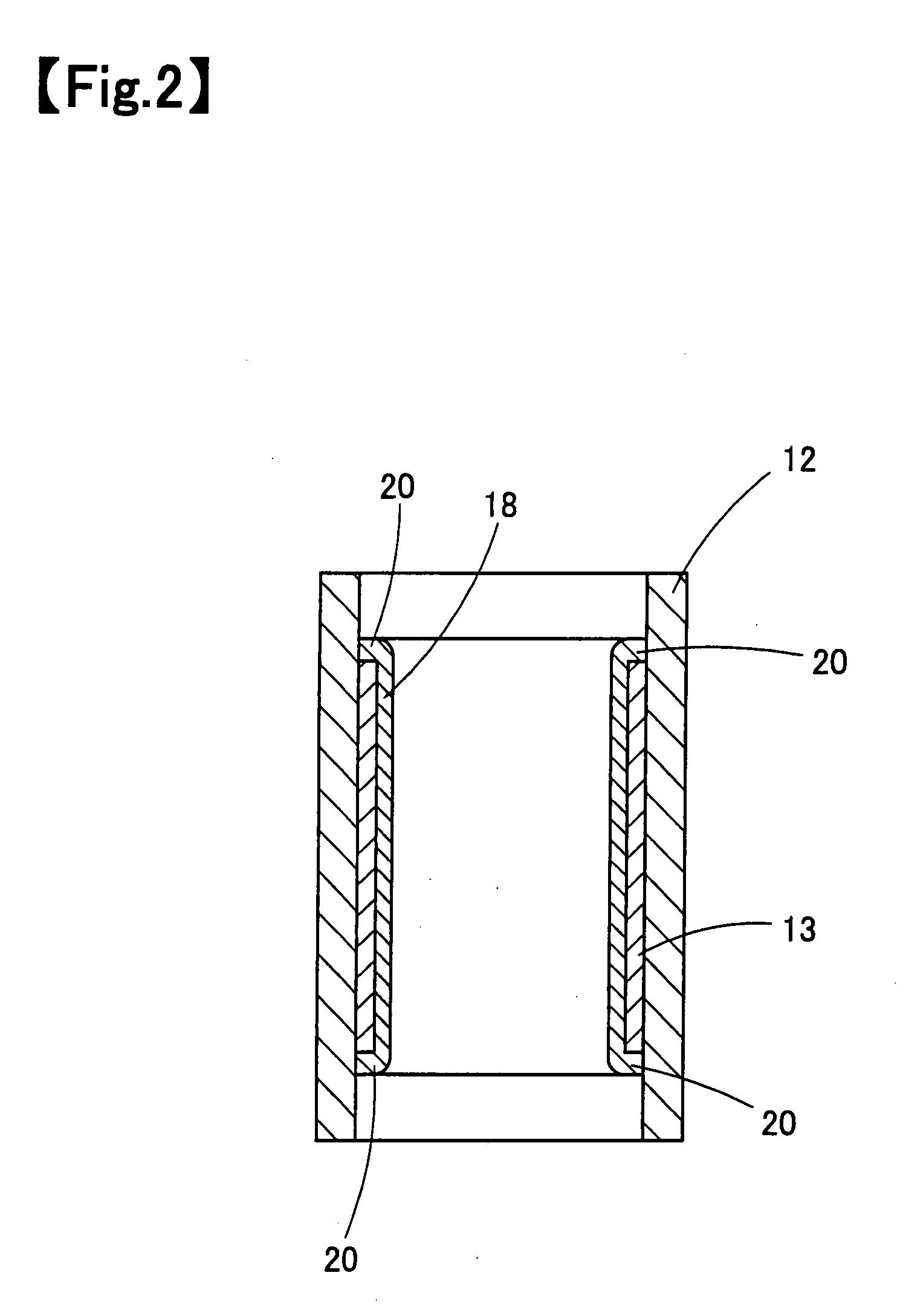
[0045]In addition, in the motor housing having a permanent magnet, according to the second feature, since the anisotropic rare earth bonded magnet is press-fitted in the housing without forming a coating layer on a contact surface in contact with the housing, the air gap between the above two is significantly decreased; hence, the magnetic resistance is decreased, and the motor performance is improved. Accordingly, high motor performance, heat resistance, and corrosion resistance in an organic solvent can be simultaneously obtained.
[0046]According to the third feature of the present invention, since the anisotropic rare earth bonded magnet used integral with the motor housing uses a phenol-novolac type epoxy resin and is press-fitted in the motor housing by heating, and the polyamide-imide-based resin coating layer formed by the infiltration treatment is provided on a surface at which the anisotropic rare earth bonded magnet and the housing is not in contact with each other, high motor properties, heat resistance, and corrosion resistance in an organic solvent can be simultaneously achieved. In this case, the infiltration treatment is a treatment in which the polyamide-imide-based resin is infiltrated in irregularities present on the surface of the anisotropic rare earth bonded magnet by using the difference between an ambient pressure and a pressure in concaves of the magnet or by using a capillary phenomenon of a resin solution.
[0047]When the anisotropic rare earth magnetic powder is used as described in the fourth and fifth feature, the magnetic properties of the bonded magnet can be significantly improved.
[0048]In accordance with the sixth feature, since the infiltration treatment of the surface layer is to immerse the anisotropic rare earth bonded magnet in a solution of the polyamide-imide-based resin under reduced-pressure conditions, air bubbles are released from the inside of the resin into the solution, and instead of the air bubbles, the polyamide-imide-based resin is infiltrated inside the resin. As a result, in addition to a further increase in the depth of the infiltration treatment, when the coating solution is applied to the magnet surface, air contained in irregularities of the magnet surface is removed, and hence formation of pinholes, caused by air which is expanded in heating and drying and is then blown out, can be prevented. In addition, since the coating layer formed by the infiltration treatment is smooth compared to the magnetic surface or a coating layer surface which is not processed by the infiltration treatment, the probability of pinhole formation in a coating layer formed on an upper layer of the formed coating layer can be remarkably decreased. As a result, corrosion resistance and swelling resistance of the bonded magnet can be improved.
[0049]According to the seventh feature of the present invention, before the anisotropic rare earth bonded magnet is immersed in the polyamide-imide-based resin solution under reduced-pressure conditions, it is placed under a reduced-pressure environment to be evacuated, and the above solution is then supplied under the reduced-pressure environment, so that the anisotropic rare earth bonded magnet is immersed in the solution. Accordingly, air bubbles are released from the inside of the bonded magnet into the solution, and instead of the air bubbles, the polyamide-imide-based resin is infiltrated in the bonded magnet. As a result, the depth of the infiltration treatment is further increased, and the reliability thereof is ensured; hence, corrosion resistance and swelling resistance of the bonded magnet can be improved.

Problems solved by technology

Hence, since the coating and the adhesion layer are present between the motor housing and the anisotropic rare earth bonded magnet, which form a magnetic circuit, an air gap on the magnetic circuit is generated, and as a result, as motor properties using this magnet, the potential ability of the anisotropic rare earth bonded magnet could not be sufficiently extracted.
Furthermore, since a bisphenol-A type epoxy resin is inferior in heat resistance, it is difficult to use the above bonded magnet for automobile application that requires heat resistance.
In addition, a common bisphenol-A type epoxy resin is coated with an epoxy resin which is the same type as the above resin; however, in this case, the corrosion resistance in an organic solvent is inferior.

Method used


Image

  • Permanent Magnet For Motor, Motor Housing, and Motor Device
  • Permanent Magnet For Motor, Motor Housing, and Motor Device
  • Permanent Magnet For Motor, Motor Housing, and Motor Device

Examples


first embodiment

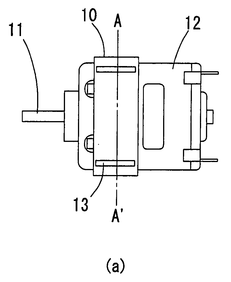
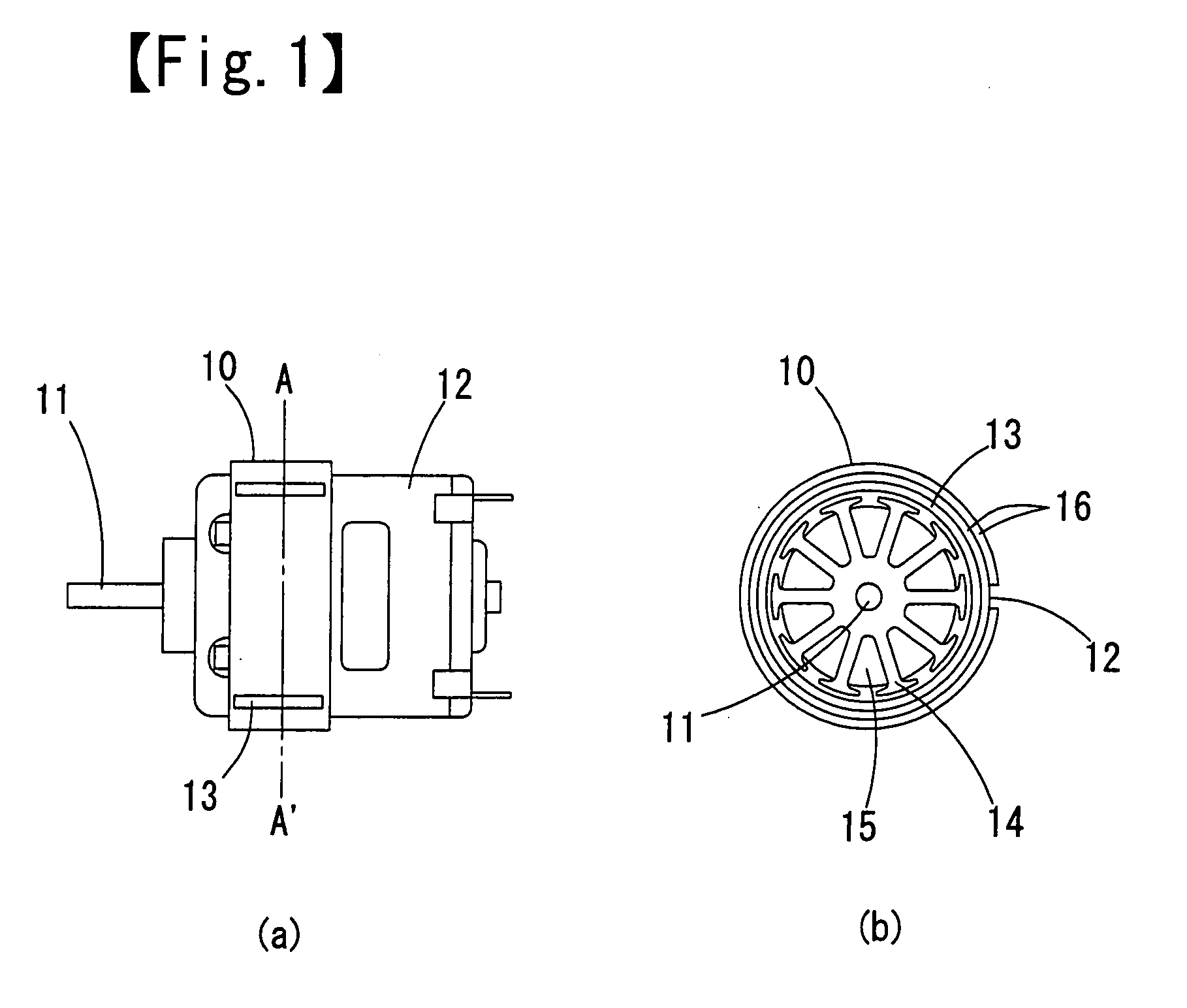
[0085]FIGS. 1(a) and 1(b) show one example of a motor device of this embodiment. FIG. 1 includes a side view (a) and a cross-sectional view (b) taken along a line A-A′. The motor device of this embodiment is formed to reduce the size of a conventional motor device, to realize a higher torque constant, and to prevent degradation in motor properties with time when it is used in an organic solvent. The motor device of this embodiment is composed of a housing 12, a hollow-cylinder shaped anisotropic rare earth bonded magnet 13, which is a permanent magnet, provided in an inner peripheral portion of the housing 12, an armature 14 provided at a central portion to form an electromagnetic rotor, coils 15 coiled around the armature 14, a rotary shaft 11 extending from a center portion of the armature 14, and a back yoke 10 provided for prevention of magnetic flux leakage. In this embodiment, an anisotropic rare earth bonded magnet is used as the bonded magnet 13. In the case in which an anis...

examples

[0113]Next, various properties of the anisotropic rare earth bonded magnet were measured. The measurement will be described below.

[0114]The viscosity properties of a phenol-novolac type epoxy resin used as the binder of the anisotropic rare earth bonded magnet and the viscosity properties of a bisphenol-A type epoxy resin which was heretofore used were measured. The results are shown in FIG. 5. Accordingly, it is understood that the minimum value of the viscosity of the phenol-novolac type epoxy resin used in the present invention is smaller than that of the bisphenol-A type epoxy resin by approximately one order of magnitude. In addition, it is found that the temperature of the phenol-novolac type epoxy resin at the minimum value is lower than that of that of the bisphenol-A type epoxy resin at the minimum value. When the orientation treatment of the magnetic powder is performed in a region in which the viscosity of the resin is lowest, the magnetic field may be decreased, and henc...


PUM


Abstract

[Object] To improve resistance of a motor device against an organic solvent and to suppress degradation in performance of the motor device with time.[Solving Means] In a motor device, an excitation magnet is formed using a hollow-cylinder shaped anisotropic bonded magnet 13. This bonded magnet 13 is press-fitted in a housing 12 and is held. The bonded magnet 13 is formed of a hollow-cylinder shaped anisotropic rare earth bonded magnet which is obtained by compounding an anisotropic rare earth magnet powder with a phenol-novolac type epoxy resin, followed by molding. The anisotropic rare earth bonded magnet 13 is press-fitted along an inner peripheral portion of the housing 12, and on an exposed surface layer of the anisotropic rare earth bonded magnet press-fitted in the housing, a coating layer is formed by an infiltration treatment using a polyamide-imide-based resin.

Description

TECHNICAL FIELD[0001]The present invention relates to a permanent magnet for motor, a motor housing having a permanent magnet, and a motor device. In more particular, the present invention relates to a motor housing which uses an anisotropic rare earth bonded magnet as a permanent magnet, can reduce the size of a motor device and realize a higher torque output, has heat resistance, and can be used in an environment, such as in an organic solvent (in a liquid and a gas phase), and relates to a motor device. For example, the motor housing and the motor device are effectively applied to a fuel pump which is used while it is immersed in petroleum, such as light oil or gasoline for automobiles.BACKGROUND ART[0002]In recent years, in the field of motors, anisotropic rare earth bonded magnets have started to be used, and the motor performance has been significantly improved. However, needs for higher performance and reduction in size have been strong, and further improvement in motor perfo...

Claims


Application Information

Patent Timeline
IPC IPC(8): H02K5/02H01F7/02H02K5/04F04B17/03
CPCF02M37/10F04D5/002F04D13/06H01F1/0572H02K15/03H01F1/0578H01F1/059H01F41/026H02K1/17H01F1/0573
Inventor HONKURA, YOSHINOBUMATSUOKA, HIROSHIKANO, ATSUSHINOGUCHI, KENJIMITARAI, HIRONARIKAN, SATORU
Owner AICHI STEEL
Learn More