
Sialon Insert and Cutting Tool Equipped Therewith

a technology of cutting tools and inserts, which is applied in the direction of cutting inserts, turning machine accessories, manufacturing tools, etc., can solve the problems of reducing the life of the tool, affecting the roughness of the surface the dimensional accuracy of the cut material, so as to improve the fuel consumption rate of vehicles, reduce the weight of vehicle materials, and reduce the cost of production.

Inactive Publication Date: 2008-05-22
NGK SPARK PLUG CO LTD
View PDF17 Cites 12 Cited by
  • Summary
  • Abstract
  • Description
  • Claims
  • Application Information

AI Technical Summary

Benefits of technology

[0019]The insert according to the first invention is made of a Sialon. They not only have the cutting edge with high strength but also make it possible to control decomposition and wear due to the chemical reaction between the workpiece and the insert material of the tool. They are also able to control mechanical damage, a typical example of which is abrasive wear that often happens when Sialon is employed as the material for cutting tools, and substantially prolong the life of the tools. The Sialon insert especially according to the first invention and the cutting tool employing this insert according to the fourth invention are able to work materials difficult to cut, such as ductile iron and heat-resistant alloy, as well as normal gray cast iron, at a high speed, with the cutting edges worn and chipped off little, which imparts a prolonged life to the insert and tool. When they are used for rough cutting, they are excellent in the wear resistance of the cutting edges of the tool, which affects the roughness of the surface and the dimensional accuracy of the workpiece, and able to continue cutting for a long time with keeping the roughness and the accuracy within preferable ranges.
[0020]The insert according to the second invention is made of a Sialon. They not only have the cutting edge with high strength but also make it possible to control decomposition and wear due to the chemical reaction between the workpiece and the insert material of the tool. Also, by limiting the proportion of the dissolved aluminum A in the solid solution, mechanical damage, a typical example of which is abrasive wear, to the cutting edges can be reduced, and the life of the tool can be prolonged substantially. The Sialon insert especially according to the second invention and the cutting tool employing this insert according to the fourth invention are best appropriate for cutting materials such as FC materials. When they are used for rough cutting, they are excellent in the wear resistance of the cutting edges of the tool, which affects the roughness of the surface and the dimensional accuracy of the workpiece, and able to continue cutting for a long time with keeping the degree and the accuracy within preferable ranges.
[0021]The insert according to the third invention is a Sialon insert with the controlled composition and structure of the sintered body, which is excellent in the strength and the hardness at high temperatures, and the wear resistance. Chipping off due to adhesion and the resulting damage is also controlled with the insert. Therefore the insert and the cutting tool employing this insert according to the fourth invention can enjoy a very prolonged life even when they are employed for cutting materials that are difficult to cut, as well as ordinary materials. As a result, high-speed cutting of materials that are difficult to cut, such as ductile iron and heat-resistant alloy, becomes possible, which contributes to a reduction in the cutting cost and an improvement in the cutting efficiency.

Problems solved by technology

In actuality, however, Sialon cutting tools were used only for rough-cutting heat-resistant alloy that is difficult to cut.
The wear resistance of the cutting edge of the Sialon insert, which affects the roughness of the surface of a cut material and the dimensional accuracy of the cut material, has not been considered seriously.
In recent years, the weight saving of vehicle materials including FC materials as a most used material has been a big problem to improve the fuel consumption rate of the vehicles.
Silicon nitride is a covalent bonding material, and the defect is that silicon nitride is prone to decompose into silicon atoms and nitrogen atoms under a high temperature caused by high-speed cutting.
The decomposition of silicon nitride in the cutting edge of an insert leads to wear of and damage to the cutting edge.
The wear of the cutting edge results in deterioration in the roughness of the surface and the dimensional accuracy of the workpiece.
Finally, it becomes impossible to further use the tool, which means that the life of the tool has expired.
As explained above, people skilled in the art consider that the wear of and damage to the cutting edge is mainly due to chemical wear caused by the chemical reaction between the cutting edge of the tool and the workpiece.
Besides, it was found out that the material was liable to cause abrasive wear, and growth of the abrasive wear, in turn, caused chipping-off of the cutting edge of the tool.
However, the addition of titanium nitride or aluminum oxide is prone to cause deterioration in the strength.
More specifically, the addition of the former is liable to lower the strength at high temperatures due to the difference between the thermal expansion coefficient of titanium nitride and that of silicon nitride.
On the other hand, the addition of the latter is liable to reduce the strength because the addition changes silicon nitride to the Sialon.
Therefore it was difficult to balance the properties of the insert material.
The skilled artisan had difficulty in producing tools with a sufficiently long life especially when the tools were used to cut materials difficult to cut, such as ductile iron, at a high speed.

Method used


Image

  • Sialon Insert and Cutting Tool Equipped Therewith
  • Sialon Insert and Cutting Tool Equipped Therewith
  • Sialon Insert and Cutting Tool Equipped Therewith

Examples


working examples

A. Working Examples A-U and Comparative Examples *1-*11 for the First Invention

(1) Preparation of Insert

[0070]Powdery raw materials were prepared by mixing α-Si3N4 powder with an average particle size of 0.5 μm; a sintering aid selected from the group consisting of Sc2O3 powder with an average particle size of 1.0 μm, Y2O3 powder with an average particle size of 1.3 μm, CeO2 powder with an average particle size of 1.7 μm, Dy2O3 powder with an average particle size of 0.9 μm, Er2O3 powder with an average particle size of 1.0 μm, Yb2O3 powder with an average particle size of 1.1 μm, and Lu2O3 powder with an average particle size of 1.0 μm; and further Al2O3 powder with an average particle size of 0.4 μm and AlN powder with an average particle size of 1.3 μm, respectively in the amounts shown in Table 1 so that the powdery raw materials had the compositions shown in the same table. Then, each of the powdery raw materials was placed in a pot mill, the inside walls of which was made of S...

working examples 1-23

B. Working Examples 1-23 and Comparative Examples 1-7 for the Second Invention

(1) Preparation of Insert

[0084]Powdery raw materials were prepared by mixing α-Si3N4 powder with an average particle size of 0.5 μm; a sintering aid selected from the group consisting of Sc2O3 powder with an average particle size of 1.0 μm, Y2O3 powder with an average particle size of 1.1 μm, CeO2 powder with an average particle size of 1.7 μm, Dy2O3 powder with an average particle size of 0.9 μm, Er2O3 powder with an average particle size of 1.0 μm, Yb2O3 powder with an average particle size of 1.1 μm, and Lu2O3 powder with an average particle size of 1.0 μm; and further Al2O3 powder with an average particle size of 0.4 μm, AlN powder with an average particle size of 1.3 μm, TiN powder with an average particle size of 1.5 μm, TiC powder with an average particle size of 1.0 μm, and TiCN powder with an average particle size of 1, 0 μm respectively in the amounts shown in Table 2. Then, each of the powdery r...

working examples 24-41

C. Working Examples 24-41 and Comparative Examples 8-16 for the Third Invention

(1) Preparation of Throwaway Tip

[0115]Powdery raw materials were prepared by mixing α-Si3N4 powder with an average particle size of 0.5 μm; a sintering aid selected from the group consisting of Sc2O3 powder with an average particle size of 1.0 μm, Y2O3 powder with an average particle size of 1.3 μm, CeO2 powder with an average particle size of 1.7 μm, Dy2O3 powder with an average particle size of 0.9 μm, Er2O3 powder with an average particle size of 1.0 μm, Yb2O3 powder with an average particle size of 1.1 μm, and Lu2O3 powder with an average particle size of 1.0 μm; and further Al2O3 powder with an average particle size of 0.4 μm, AlN powder with an average particle size of 1.3 μm, and TiN powder with an average particle size of 1.5 μm respectively in the amounts shown in Table 3. Then, each of the powdery raw materials was placed in a pot mill, the inside walls of which was made of Si3N4, with Si3N4 bal...


PUM

PropertyMeasurementUnit
thermal conductivityaaaaaaaaaa
bending strengthaaaaaaaaaa
temperatureaaaaaaaaaa

Abstract

This invention provides a long-life Sialon insert, the cutting edge of which is resistant to wear and hard to fracture, and a cutting tool equipped with the Sialon insert.Provided are a Sialon insert made of a Sialon sintered body including a Sialon phase comprising an α-Sialon and a β-Sialon, and at least one element, originating from a sintering aid, selected from the group consisting of Sc, Y, Dy, Yb, and Lu in an amount of 0.5 to 5 mol % in terms of an oxide thereof, wherein an α-value, which shows the proportion of the α-Sialon in the Sialon phase, is from 10% to 40%; the β-Sialon has a value of Z from 0.2 to 0.7 wherein Z is a variable of the formula Si6-ZAlZOZN8-Z and within a range: 0<Z≦4.2; and the sintered body has an average thermal expansion coefficient of 3.5×10⁻⁶ / K or less at temperatures of room temperature to 1000° C., and a thermal conductivity of 10 W / m·K or more at temperatures of room temperature to 1000° C., and a cutting tool comprising a holder equipped with the Sialon insert.

Description

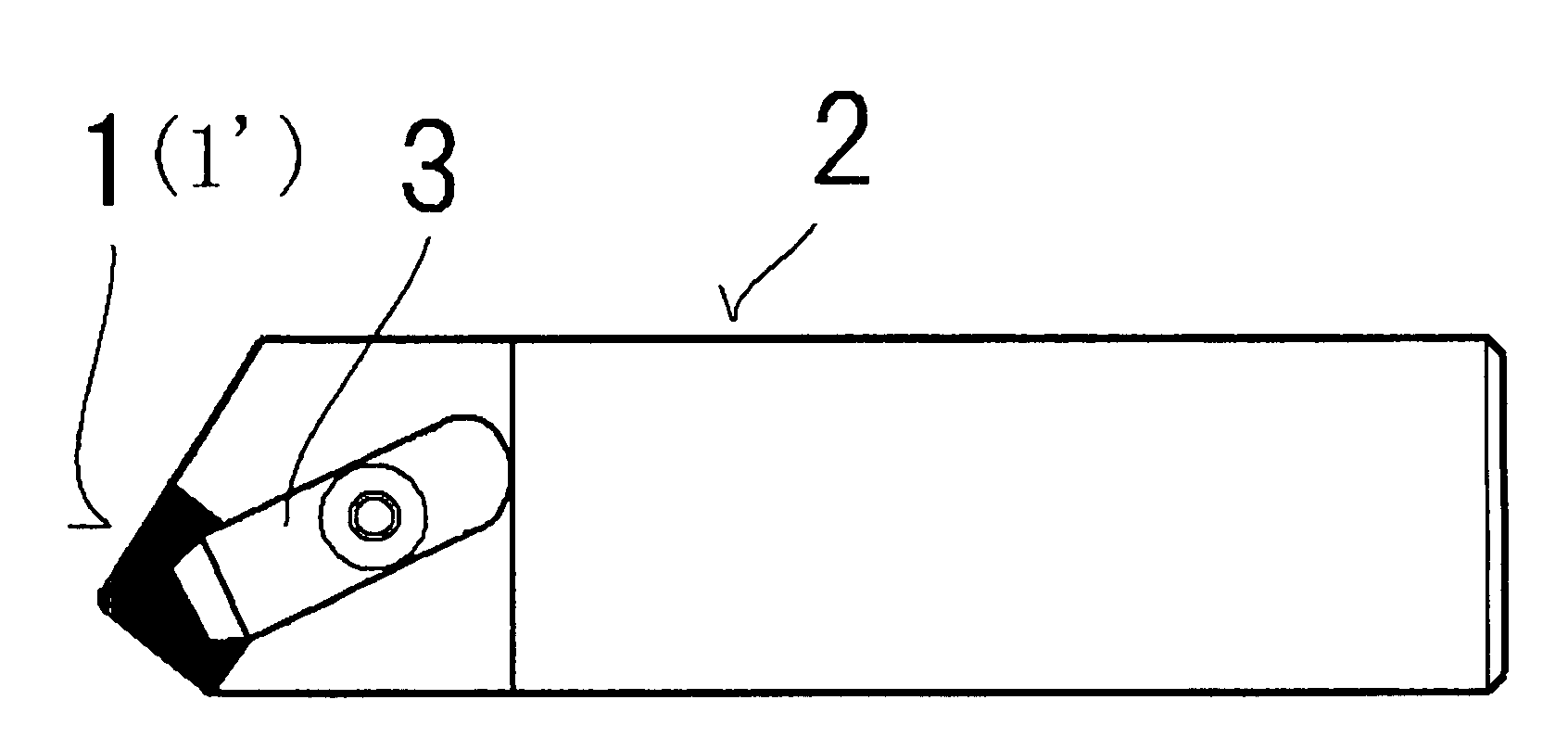
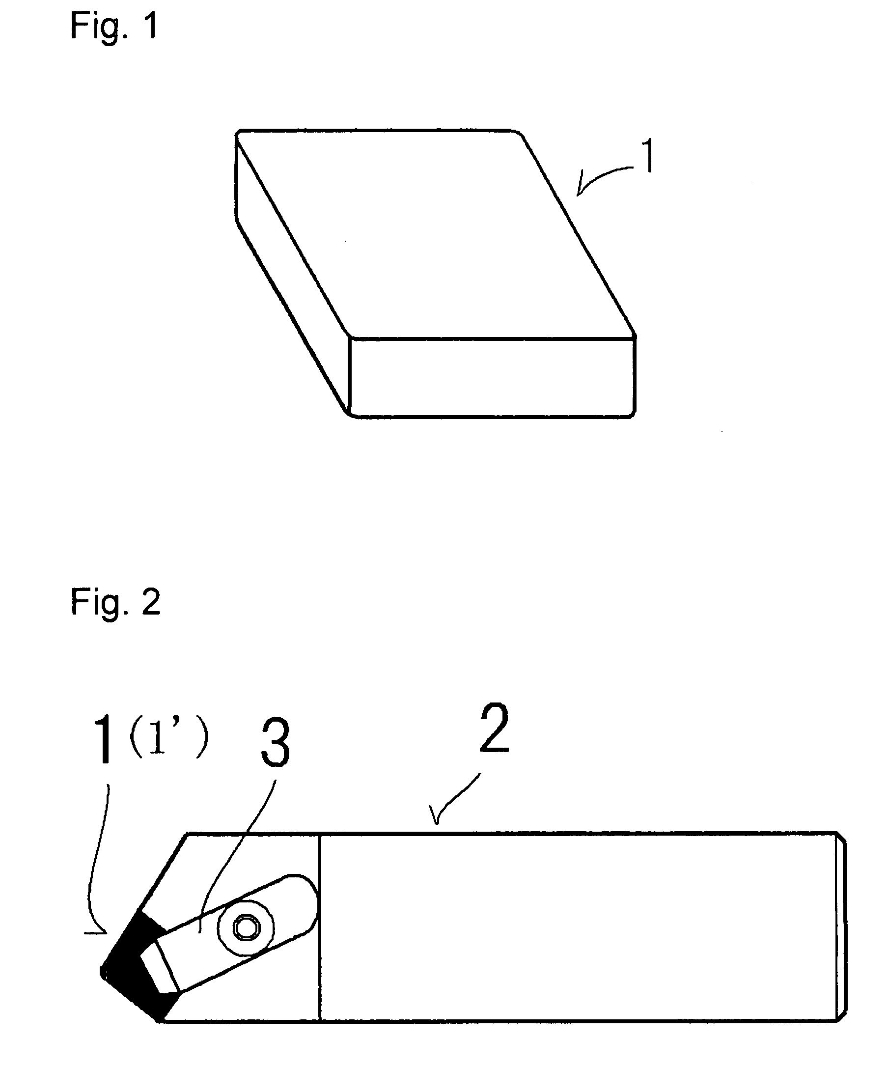
TECHNICAL FIELD[0001]The present invention relates to a Sialon insert and a cutting tool equipped with at least one Sialon insert. In more particular, the present invention relates to a Sialon insert, the cutting edge of which is resistant to wear and hard to fracture, which provides the insert with a long life, and a cutting tool equipped with the Sialon insert.BACKGROUND ART[0002]Cutting tools typically have a support, called a holder, such as a holder 2 of a cutting tool for working outer peripheral faces shown in FIG. 2 or a holder for a milling cutter shown in FIG. 5, and at least one insert, which is a disposable cutting edge that is often called “throwaway tip” or “edge-changing insert”, fixed to an end of the support. Materials for the insert are chosen, depending on kinds of workpieces, cutting processes, and cutting speeds. Examples of the materials are cemented carbides, cermets, ceramics, or CBNs, or these materials, the surfaces of which are coated with films. Among the...

Claims


Application Information

Patent Timeline
Patent Type & Authority Applications(United States)
IPC IPC(8): C04B35/599
CPCB23B27/141C04B2235/9607B23B2200/283C04B35/597C04B35/6261C04B35/638C04B35/6455C04B2235/3217C04B2235/3224C04B2235/3225C04B2235/3229C04B2235/3843C04B2235/3856C04B2235/3865C04B2235/3878C04B2235/3886C04B2235/5436C04B2235/5445C04B2235/656C04B2235/658C04B2235/661C04B2235/766C04B2235/767C04B2235/80C04B2235/85B23B2200/242
Inventor ABUKAWA, KOHEITOYODA, RYOJIKOMURA, ATSUSHI
Owner NGK SPARK PLUG CO LTD
Learn More