
Apparatus and method for forming an opening in a concrete wall system

a technology of concrete wall and opening, which is applied in the direction of building components, building material handling, construction, etc., can solve the problems of affecting the construction efficiency affecting the quality of the construction site, and affecting the quality of the construction. , to achieve the effect of reducing waste, increasing design flexibility, and reducing scrap at the jobsi

Inactive Publication Date: 2008-05-22
2M SQUARED
View PDF24 Cites 16 Cited by
  • Summary
  • Abstract
  • Description
  • Claims
  • Application Information

AI Technical Summary

Benefits of technology

[0004]It is one aspect of the present invention to provide a customizable window and / or door buck. More specifically, embodiments of the present invention are constructed of members that are composed of wood and insulation that interconnect to form the window or door buck. In addition, the individual members of the window or door buck may be cut to any desired size thereby reducing waste and increasing design flexibility. More specifically, in the case of cast-in-place wall panel construction, often chemically treated wood, usually larger that what is required to form the members of a buck, are cut at the job site and assembled to form bucks wherein any excess wood is discarded. One advantage of embodiments of the present invention is that the individual buck members, as described in greater detail below, are assembled off-site using materials of dimensions that generally coincide with the desired window, door, or other opening shape wherein scrap at the jobsite is reduced or eliminated. More specifically, in the United States, timber is generally cut in the forest in 24 foot lengths. At the mill the timber is cut into three 8 foot lengths, an 8 foot and a 16 foot length, a 10 foot and a 14 foot length or two 12 foot lengths. These standard lengths must be modified at the job site to yield the desired opening wherein the excess is discarded. Conversely, the buck material of a customized length may be delivered to the job site and cut into separate buck members wherein the excess is significantly reduced. Embodiments of the present invention employ 47% less wood than bucks constructed of dimensional lumber. Furthermore, the buck members retain the advantages of wood, thereby facilitating sawing, drilling and general workability while being less expensive than wood alone or vinyl. The buck members are also eco-friendly because they eliminate the need for chemically treated wood products as the wood incorporated into the buck members does not contact the concrete. Another advantage of the buck members as described herein is that less heat transfer occurs because the buck material includes insulation as opposed to a wood / concrete interface. The present buck system is typically less costly, including material and labor costs, than buck systems of the prior art and provides greater design options.
[0005]It is another aspect of the present invention to provide bucks that may be employed in various concrete wall construction schemes, such as cast-in-place walls, prefabricated tilt-up walls (which may include a low density insulated core), or concrete walls that employ interlocking insulated concrete forms, as described in detail below. In the case of a cast-in-place wall, after a first wall form and associated reinforcement are located, the window buck is placed and secured to the reinforcing members and a second wall form. Yet another advantage of this building method, in addition to reduction in waste and omission of shims, is that workers can help ensure concrete is sufficiently placed under the window buck. More specifically, an aperture, in some embodiments about 1.5 to 6 inches in diameter, can be integrated on-site into a lower member of a buck to allow for vibrational concrete manipulation that causes the concrete to fill in the area under the window buck. The aperture can then be plugged to prevent excess concrete from escaping and / or to restore the continuity of the lower buck member.
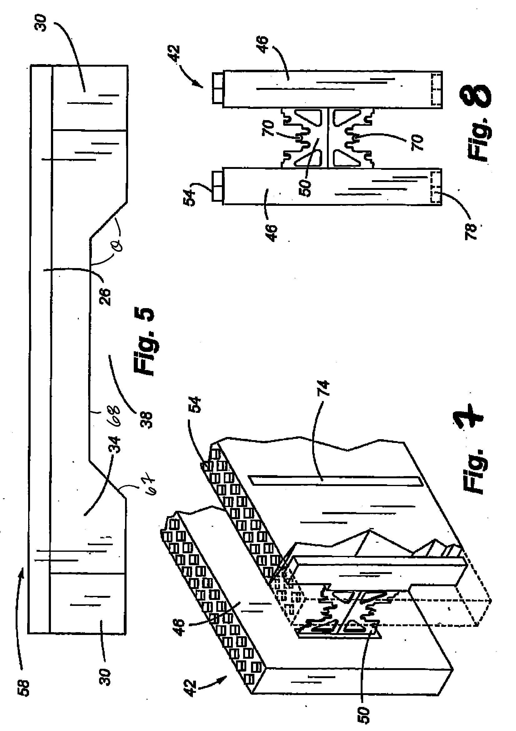
[0006]One skilled in the art will appreciate that embodiments of the present invention may be incorporated into prefabricated concrete wall panels. For example, prior to placing the concrete into a horizontally-oriented form, a window buck may be located to define the desired window opening. Further, some embodiments of the present invention are adapted to be used with insulated panels spaced by a web. These insulated concrete forms (“ICF”) are usually light and stackable, thereby allowing workers to easily construct a wall of substantial size without the aid of heavy machinery. Embodiments of the present invention additionally provide a novel way of including a rebar securing member within the space between the two adjacent parallel insulation panels that make up the ICF.
[0007]It is yet another aspect of the invention to provide an indication of buck member length. That is, embodiments of the invention include ruled markings to help workers to easily estimate or customize the length of individual buck members prior to buck assembly. The markings maybe spaced in any common unit of length, including every inch, centimeter, yard, foot, meter, etc. In addition, other markings or colors may be employed to indicate size, such as buck depth, or to designate compatibility with other building materials, or to enhance assembly. Trademarks may also be included.

Problems solved by technology

One way to form a window or door opening is to cut and remove a section from the finished, cured wall which is costly and which can damage other portions of the wall.
One drawback of bucks used today is that they are difficult to locate, are heavy, are size specific, are generally not insulated, and often wasteful.
Further, bucks found in the art are often constructed of vinyl or non-eco-friendly wood products that include chemical additives to prevent wood degradation attributed to wood / concrete contact.

Method used


Image

  • Apparatus and method for forming an opening in a concrete wall system
  • Apparatus and method for forming an opening in a concrete wall system
  • Apparatus and method for forming an opening in a concrete wall system

Examples


Embodiment Construction

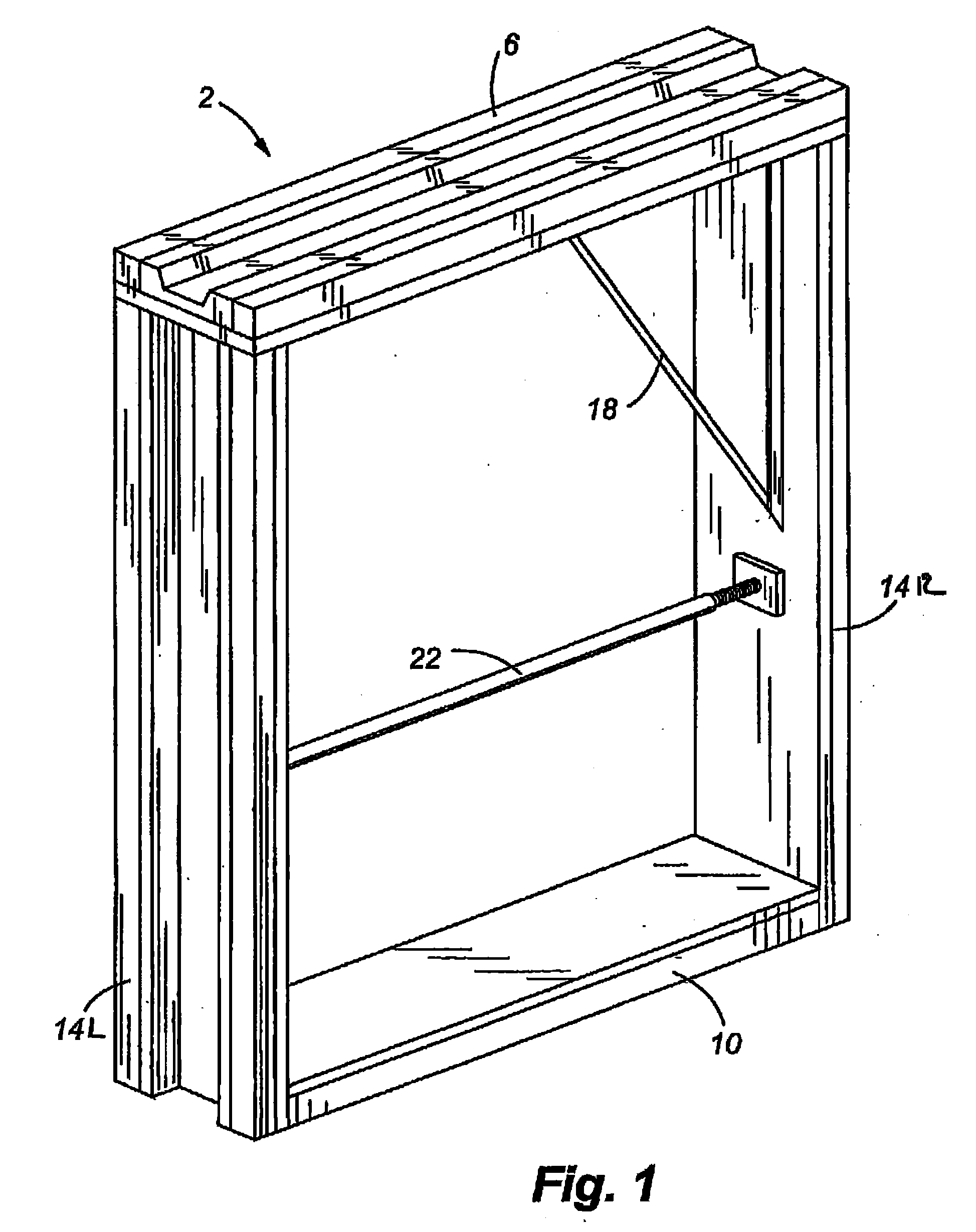
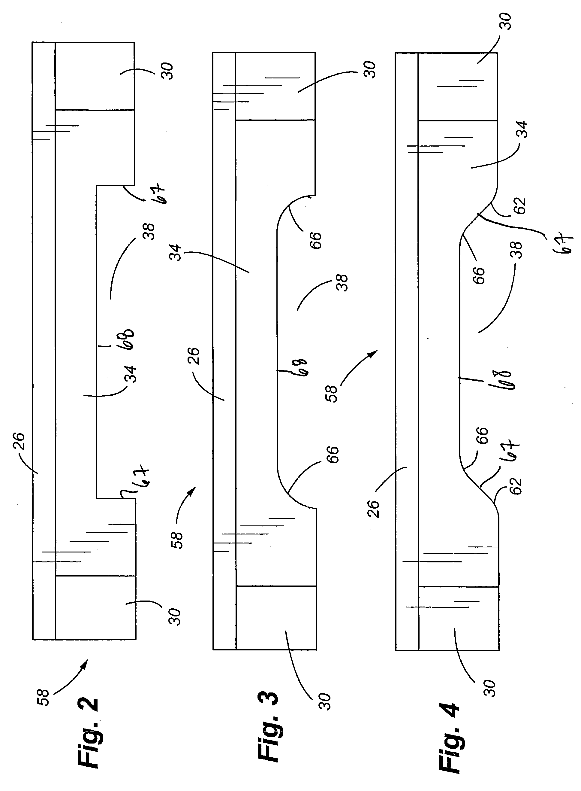
[0025]Referring now to FIGS. 1-13, a system for creating an opening in a concrete wall is provided. More specifically, a window buck 2 that is comprised of an upper buck member 6, a lower buck member 10 and two lateral buck members 14 positioned therebetween is generally provided. The buck members are maintained approximately square during forming with a brace 18. An adjustable brace 22 may also be employed to ensure that the lateral buck members 14 and / or the upper buck member 6 and the lower buck member 20 do not bow inward when concrete is placed into the form. The buck members are generally comprised of a panel 26 with beams 30 interconnected thereto via fasteners, adhesives, etc. However, the buck members may be formed from a unitary form or extruded. The space between the beams 30 contains an insulative material 34 that may include a keyway 38. The completed window buck 2 is integrated into a cast-in-place wall form, prefabricated tilt-up wall form, or into a system of interlo...


PUM


Abstract

A method and apparatus for forming an opening in a concrete wall is provided. More specifically, interlocking concrete forms comprising parallel spaced insulation panels are provided for receipt of concrete. Any openings, i.e. such as for windows and doors, are accommodated within the insulated concrete forms by way of a customizable buck. The buck members utilize less material than those of the prior art, and are easily customized to yield a required opening size. The placement of concrete into the form yields a concrete wall with the desired window or door opening.

Description

[0001]This application claims the benefit of U.S. Provisional Patent Application Ser. No. 60 / 866,365, filed Nov. 17, 2006, the entire disclosure of which is incorporated by reference herein.FIELD OF THE INVENTION[0002]The present invention relates generally to a method and apparatus for forming a window or door opening in a concrete wall.BACKGROUND OF THE INVENTION[0003]Pre-cast concrete wall panels or cast-in-place concrete walls often require window and door openings. One way to form a window or door opening is to cut and remove a section from the finished, cured wall which is costly and which can damage other portions of the wall. Alternatively, it is known to incorporate a void, i.e., a “buck”, into a concrete wall form to define the required opening in the wall panel. Bucks are usually transported to, or fabricated at, a construction site, in the case of a cast-in-place wall or, in the case of prefabricated wall panel construction, assembled at a factory. One drawback of bucks ...

Claims


Application Information

Patent Timeline
Patent Type & Authority Applications(United States)
IPC IPC(8): E06B1/04
CPCE04G21/1841E04G21/1858
Inventor MILL, ALAN
Owner 2M SQUARED
Learn More