
Low-melting point superabrasive tools and associated methods

a superabrasive tool and low-melting point technology, applied in the direction of grinding device, abrasive surface conditioning device, metal-working apparatus, etc., can solve the problems of abrasive slurry, abrasive dust coming from workpieces, and the accumulation of polishing debris coming from workpieces, so as to achieve the effect of improving the wetting and low-melting poin

Inactive Publication Date: 2008-04-24
SUNG CHIEN MIN
View PDF6 Cites 38 Cited by
  • Summary
  • Abstract
  • Description
  • Claims
  • Application Information

AI Technical Summary

Benefits of technology

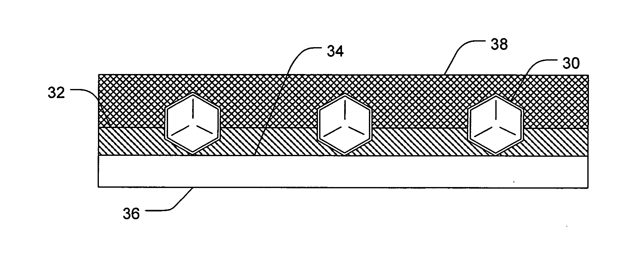
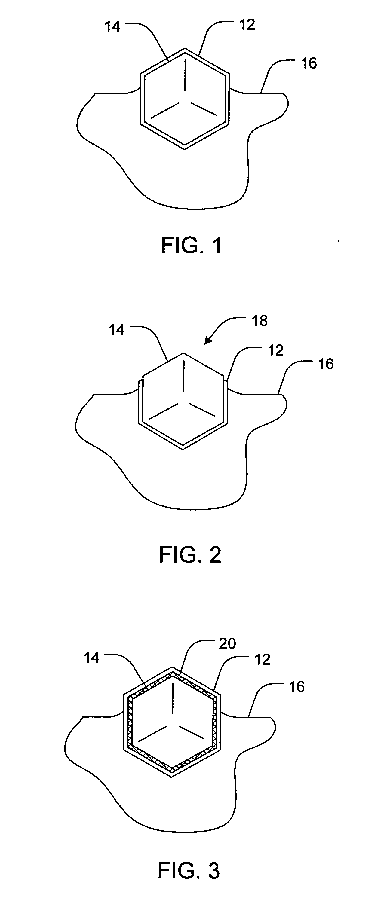
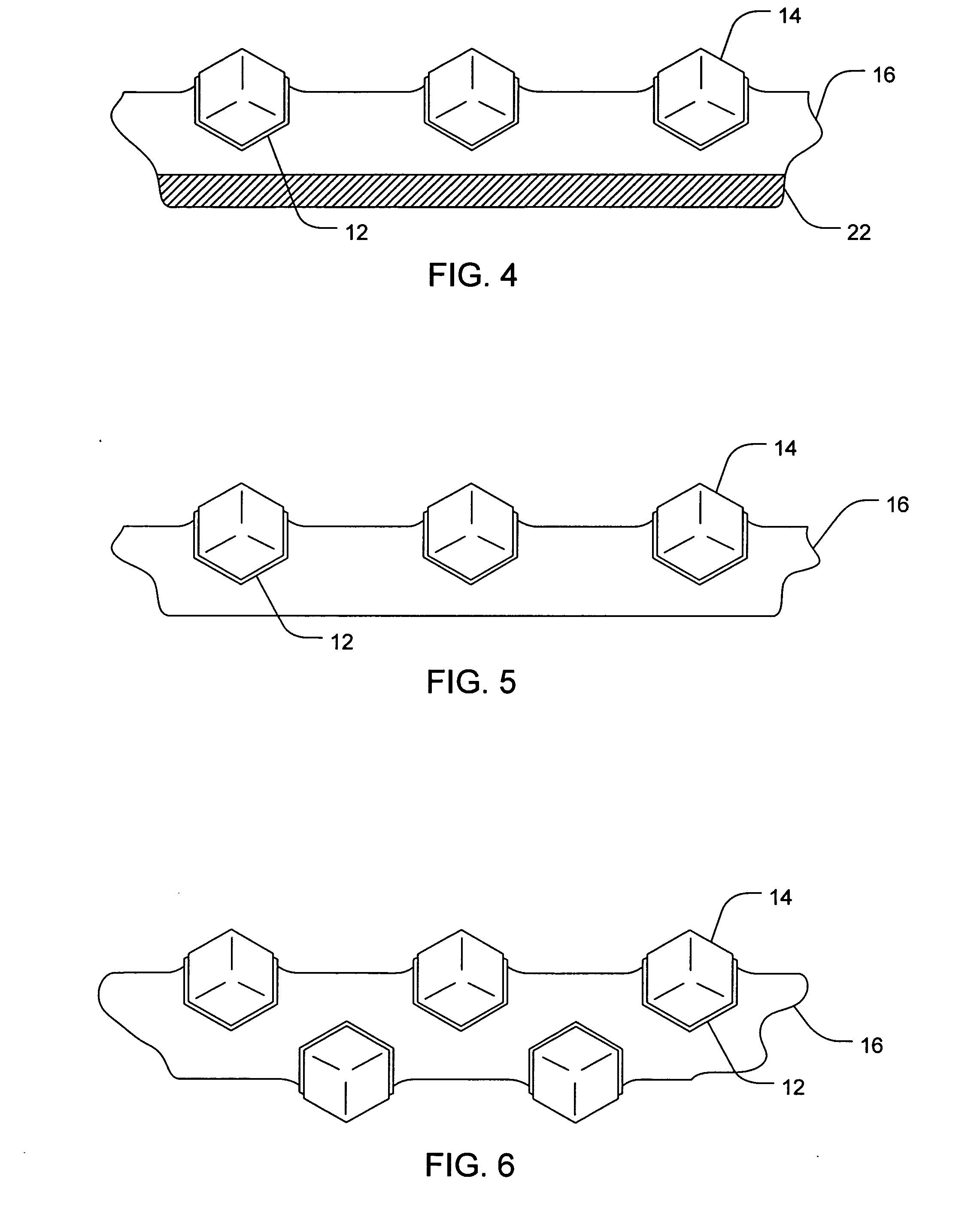
[0011]Numerous braze materials having low-melting temperatures are contemplated, all of which are considered to be within the scope of the present invention. Non-limiting examples may include Al, Ag, Sb, Zn, Pb, Cd, Cu, Tl, Bi, Sn, In, Ga, and combinations thereof. The braze materials may also include alloys having low-melting temperatures. Examples may include, without limitation, Al—Si, Babbit, Cu—Mg, Al—Cu, Al—Mg, Cu—Zn, Al—Ge, Cu—Sn, Al—Sn, Sn—Zn, Sn—Tl, Sn—Pb, Sn—Cu—Ag, and combinations thereof.
[0012]In one aspect of the present invention, a wetting layer may be applied to the intermediate layer to improve the wetting between the reactive element and the braze. Various wetting layer materials are contemplated, non-limiting examples of which may include Si, Cu, Ni, Cr, and combinations the...

Problems solved by technology

One problem that arises with regard to maintaining the pad surface, however, is an accumulation of polishing debris coming from the work piece, the abrasive slurry, and the pad dresser.
This accumulation causes a “glazing” or hardening of the top of the pad, mats the fibers down, and thus makes the pad surface less able to hold the abrasive particles of the slurry.
These effects significantly decrease the pad's overall polishing performance.
Further, with many pads, the pores used to hold the slurry, become clogged, and the overall asperity of the pad's polishing surface becomes depressed and matted.
In addition to the tremendous density issues that already exist, with the current movement toward size reduction, ULSI has become even more delicate, both in size and materials than ever before.
There are a number of problems in attempting to provide such a pad dresser.
Generally speaking, the superabrasive particles are so small that a traditional metal matrix is often unsuitable for holding and retaining them.
However, such a variation would render a dresser useless if it were required to dress a CMP pad and achieve a uniform asperity depth of 20 μm or less, for example.
In addition to issues with properly holding very small superabrasive particles, traditional metal braze alloys have the tendency to warp and buckle during a heating process, causing additional issues in obtaining a CMP pad dresser having superabrasive particle tips leveled to within a narrow tolerance range.

Method used


Image

  • Low-melting point superabrasive tools and associated methods
  • Low-melting point superabrasive tools and associated methods
  • Low-melting point superabrasive tools and associated methods

Examples


Embodiment Construction

[0025]Definitions

[0026]In describing and claiming the present invention, the following terminology will be used in accordance with the definitions set forth below.

[0027]The singular forms “a,”“an,” and, “the” include plural referents unless the context clearly dictates otherwise. Thus, for example, reference to “a particle” includes reference to one or more of such particles, and reference to “the reactive material” includes reference to one or more of such materials.

[0028]As used herein, “superhard” and “superabrasive” may be used interchangeably, and refer to a crystalline, or polycrystalline material, or mixture of such materials having a Vicker's hardness of about 4000 Kg / mm2 or greater. Such materials may include without limitation, diamond, and cubic boron nitride (cBN), as well as other materials known to those skilled in the art. While superabrasive materials are very inert and thus difficult to form chemical bonds with, it is known that certain reactive elements, such as ch...


PUM


Abstract

Superabrasive tools and their methods of manufacture are disclosed. In one aspect, a method for making a low-melting point superabrasive tool having a plurality of superabrasive particles is provided. Such a method may include coating each of the plurality of superabrasive particles with a reactive element that chemically bonds to each of the plurality of superabrasive particles and bonding together the plurality of superabrasive particles with a molten braze that wets the reactive element at a temperature of less than about 700° C. In some aspects, the method may further include arranging the plurality of superabrasive particles on a leveling surface and bonding the plurality of superabrasive particles together with the molten braze such that, upon formation of the superabrasive tool, the plurality of superabrasive particles have been leveled by the leveling surface to an RA value of less than about 40 μm.

Description

FIELD OF THE INVENTION[0001]The present invention relates generally to tools having superabrasive particles embedded in a support matrix having a low-melting point and associated methods. Accordingly, the present invention involves the chemical and material science fields.BACKGROUND OF THE INVENTION[0002]Many industries utilize a chemical mechanical polishing (CMP) process for polishing certain work pieces. Particularly, the computer manufacturing industry relies heavily on CMP processes for polishing wafers of ceramics, silicon, glass, quartz, and metals. Such polishing processes generally entail applying the wafer against a rotating pad made from a durable organic substance such as polyurethane. A chemical slurry is utilized that contains a chemical capable of breaking down the wafer substance and an amount of abrasive particles which act to physically erode the wafer surface. The slurry is continually added to the rotating CMP pad, and the dual chemical and mechanical forces exer...

Claims


Application Information

Patent Timeline
IPC IPC(8): B24D11/00
CPCB24B53/017B24D18/00B24B53/12
Inventor SUNG, CHIEN-MIN
Owner SUNG CHIEN MIN
Learn More