Spiral flute tap

a cutting tap and flute technology, applied in the field of spiral fluted cutting taps, can solve the problems of cutting taps that cannot be cut through threaded holes or blind threaded holes, cutting taps that cannot be broken or otherwise not function at an acceptable level, and affect the overall cost of producing internal screw threads

Active Publication Date: 2008-04-24
KENNAMETAL INC +1
View PDF67 Cites 12 Cited by
  • Summary
  • Abstract
  • Description
  • Claims
  • Application Information

AI Technical Summary

Problems solved by technology

In addition, the speed of tapping, i.e., the production time that it takes to cut the internal screw thread, affects the overall cost to produce an internal screw thread.
However, a straight fluted cutting tap is not effective to cut a through threaded hole or a blind threaded hole that have a smaller diameter in materials that produce a continuous chip (e.g., ductile steels such as, for example, AISI 4340 steel).
In such a case, the continuous chips generated from the cutting operation bind in the flute of the straight fluted cutting tap and cause the cutting tap to break or otherwise not function at an acceptable level.
However, cemented carbide right-hand spiral flute cutting taps that have the flute designs are like those commonly used for high-speed steel cutting taps experience chipping when tapping small diameter threaded holes.
These right-hand spiral fluted cutting taps present cutting edges and edges at the heel of the flute that are prone to chipping due to the small included angles at the intersection of the flutes and thread flanks at these locations.
Chipping results in breakage of the cutting tap or (at a minimum) an inability of the cutting tap to function at an optimum level.
However, there are substantial differences in the cutting action of taps and drills.

Method used


Image

  • Spiral flute tap
  • Spiral flute tap
  • Spiral flute tap

Examples


Embodiment Construction

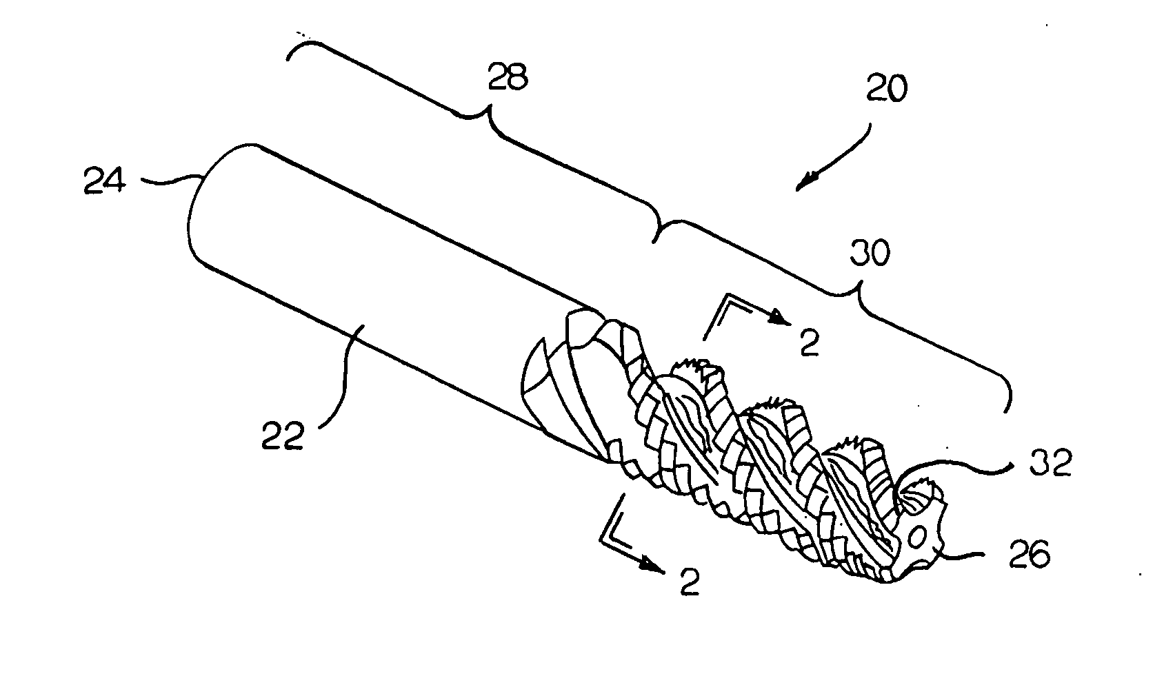
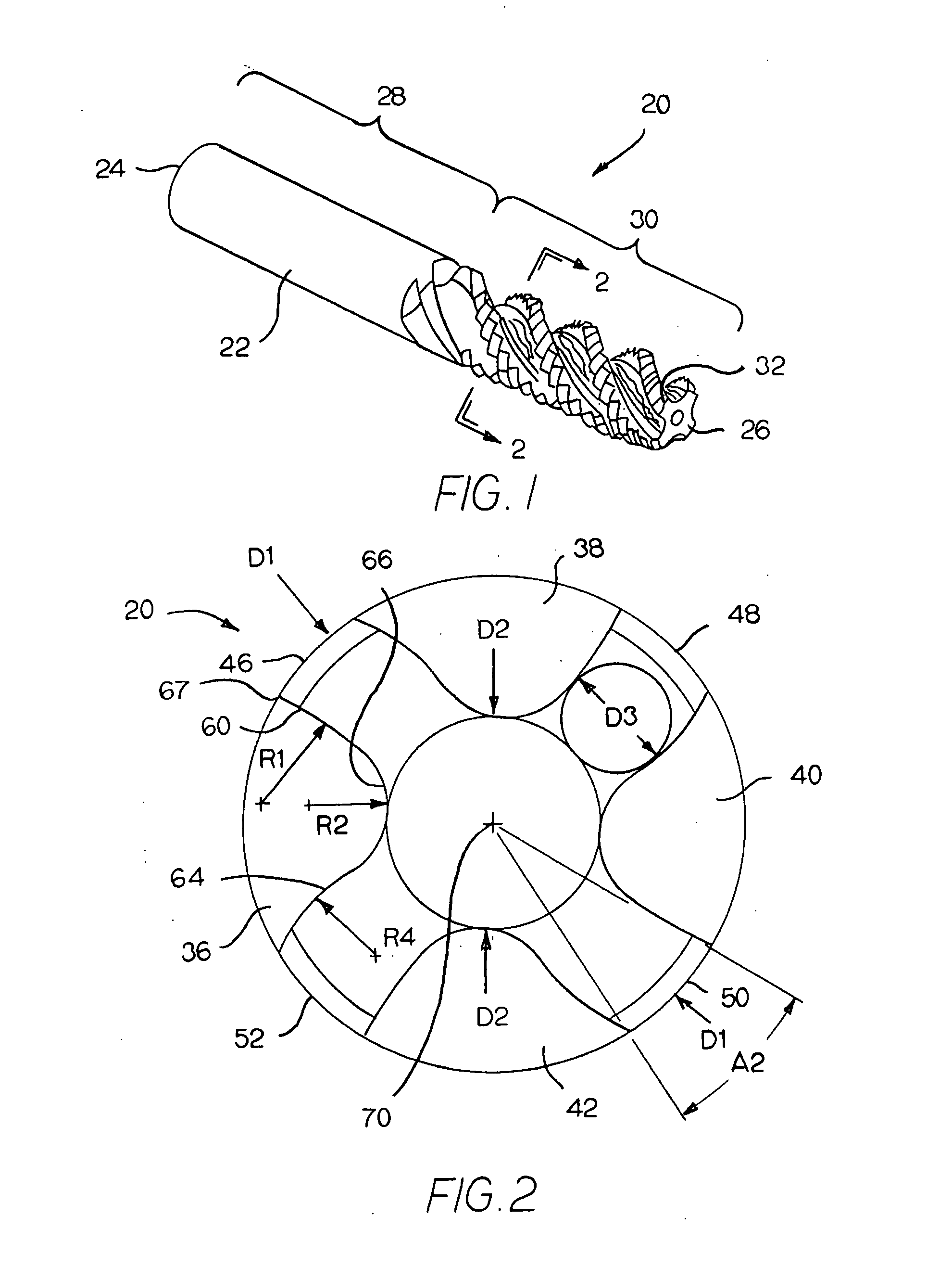
[0026]Referring to the drawings, FIG. 1 is an isometric view that illustrates a specific embodiment of the spiral fluted cutting tap (generally designated as 20) of the invention. Spiral fluted cutting tap 20 has an elongate body 22 with an opposite rearward end 24 and forward end 26. The spiral fluted cutting tap 20 has a generally smooth cylindrical shank portion shown by bracket 28 adjacent to the rearward end 24. A spiral fluted portion shown by bracket 30 begins at and extends rearwardly of the forward end 24 of the spiral fluted cutting tap 20. The spiral fluted cutting tap 20 has a cutting chamfer 32 at the axial forward end 26 thereof. As described hereinafter, the spiral fluted portion defines a cutting edge. During use, the spiral fluted cutting tap 20 is held by a machine tool by inserting the cylindrical shank portion 28 in a tool holder. It should be appreciated that the geometry of the shank portion could present a cross-section that is a square-shape.

[0027]Referring t...


PUM

PropertyMeasurementUnit
chordal hook angleaaaaaaaaaa

Abstract

A cutting tool that includes an elongate body that has a forward end and a rearward end. The elongate body has a fluted portion that beginning near and extends in a rearward direction from the forward end. The fluted portion has a flute that defines a cutting edge. The flute presents a concave cutting face wherein the concave cutting face is defined by a first radius. The flute further presents a concave core surface adjacent to the concave cutting face wherein the concave core surface is defined by a second radius. The flute presents a convex heel surface adjacent to the concave core surface wherein the convex heel surface is defined by a fourth radius.

Description

BACKGROUND OF THE INVENTION[0001]The invention relates to a cutting tool (or cutting tap) used for the production of internal screw threads in a substrate. More specifically, the invention pertains to a cutting tool (or cutting tap) that has the spiral (helical) flute geometry wherein the spiral flute cutting tap is made from cemented tungsten carbide tool materials.[0002]Mechanisms and machine components that require screw threads have a long history in technology. Specifically, the application of screw threads as fastener components is the dominate way to join parts into assemblies. Although there are many ways to generate screw threads, including both internal screw threads as well as external screw threads, experience has shown that taps (or cutting taps) are the favored way to generate the internal screw thread.[0003]There currently exist two basic tapping methods to generate internal screw threads. The dominant tapping method is by cutting material from the wall of the hole. T...

Claims


Application Information

Patent Timeline
Patent Type & Authority Applications(United States)
IPC IPC(8): B27G15/00
CPCB23G5/06B23G2200/26B23G2200/48B23G2225/28B23G2225/32Y10T408/9048B23G2225/60B23P15/52Y10T408/906Y10T408/9097B23G2225/56
Inventor HENDERER, WILLARD E.GEORGE, STEPHEN M.BURNS, STEVEN R.AKAKI, SADAYUKI
Owner KENNAMETAL INC
Why Eureka
Try Eureka