
Semiconductor device with a gate region having overlapping first conduction type and second conduction type dopants

a technology of semiconductor devices and gate regions, which is applied in the direction of semiconductor devices, electrical equipment, transistors, etc., can solve the problems of high resistance of cobalt silicide films, and achieve the effect of less likely to disperse high resistance of silicide films

Inactive Publication Date: 2008-04-17
TAKAHASHI HIROTSUGU
View PDF9 Cites 0 Cited by
  • Summary
  • Abstract
  • Description
  • Claims
  • Application Information

AI Technical Summary

Benefits of technology

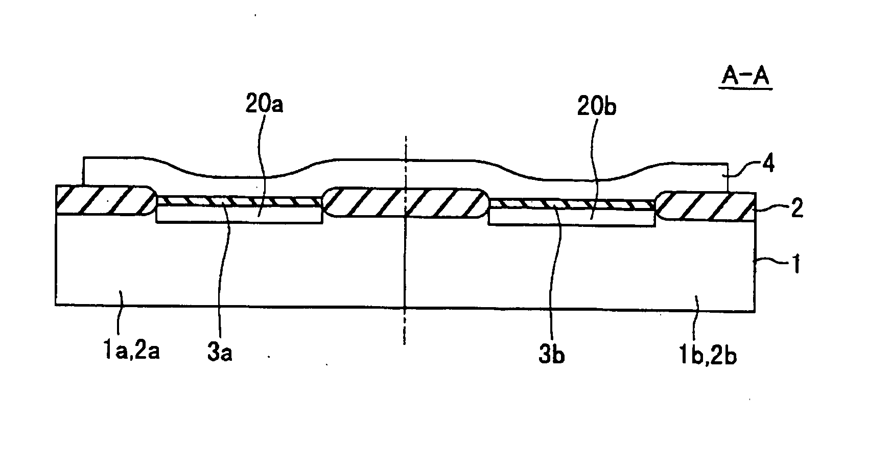
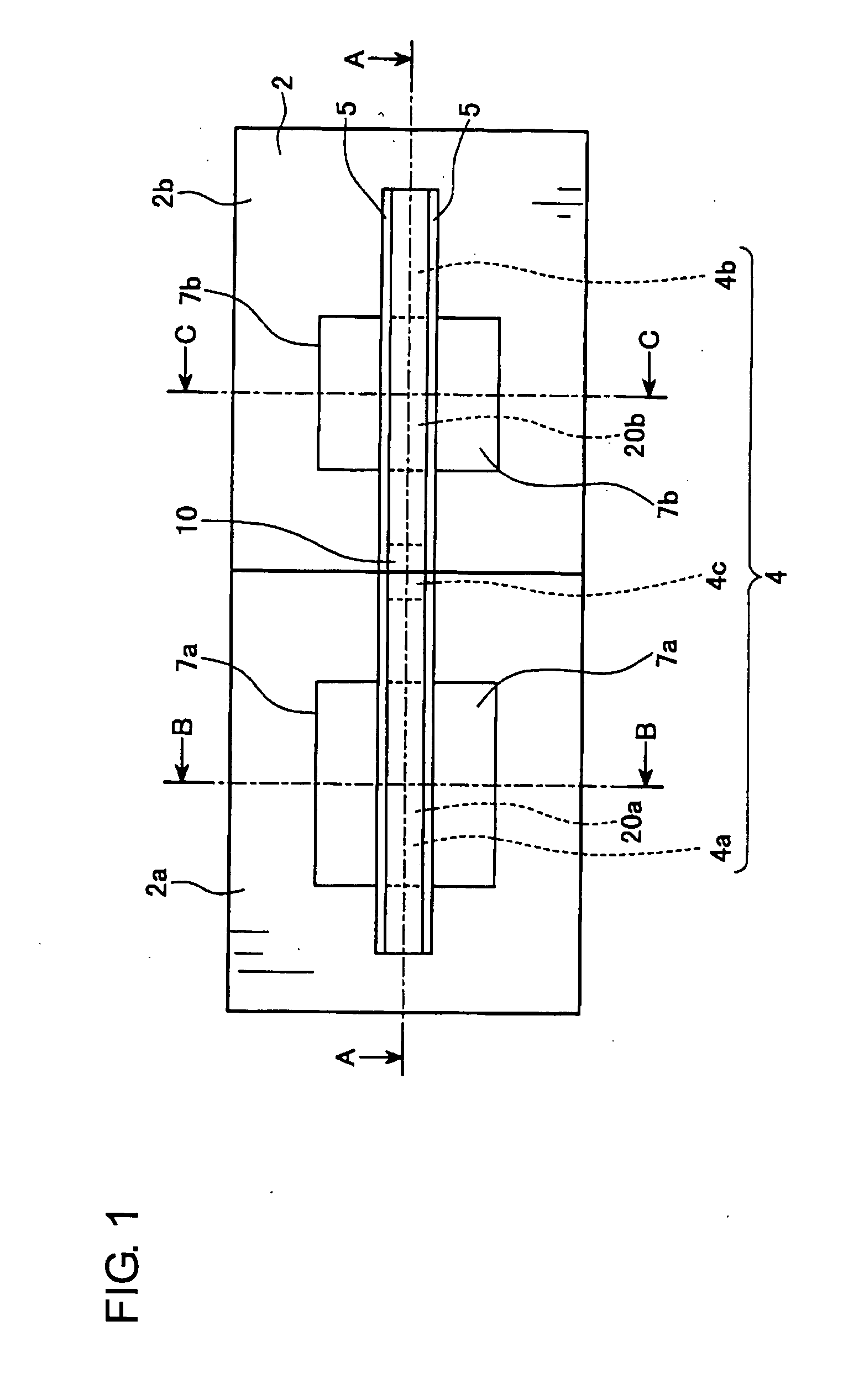
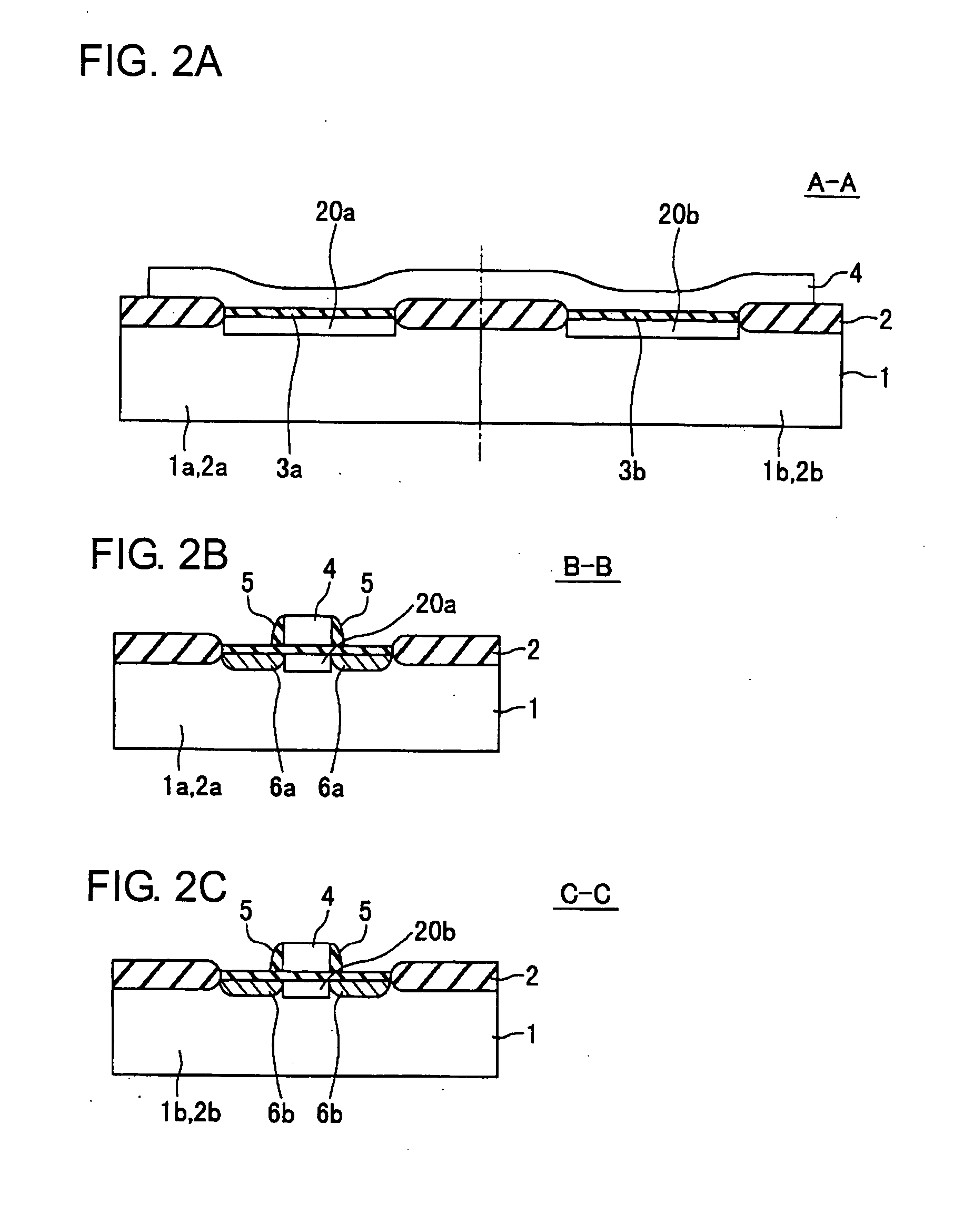
[0020] With this semiconductor device manufacturing method, the first conduction type gate region and the second conduction type gate region are formed overlapping each other at their edges. Therefore, even if the positions of the first conduction type gate region and the second conduction type gate region are misaligned, it is less likely that the region wherein the ion of dopant is not sufficiently implanted is formed in the gate electrode. Consequently, this makes the formation of the cobalt silicide film that is sufficiently formed into silicide in any part on the gate electrode easier. Hence the resistance of the silicide film is less likely to disperse high.
[0031] With this semiconductor device manufacturing method, it is also less likely that the region wherein the ion of dopant is not sufficiently implanted is formed in the gate electrode, even if the positions of the first conduction type gate region and the second conduction type gate region are misaligned. Consequently, this makes the formation of the cobalt silicide film that is sufficiently formed into silicide in any part on the gate electrode easier. Hence the resistance of the silicide film is less likely to disperse high.

Problems solved by technology

This region has a low density of dopants, thus the cobalt film is formed into silicide insufficiently, and hence the resistance of the cobalt silicide film may disperse high due to the “small diameter wire effect”.

Method used


Image

  • Semiconductor device with a gate region having overlapping first conduction type and second conduction type dopants
  • Semiconductor device with a gate region having overlapping first conduction type and second conduction type dopants
  • Semiconductor device with a gate region having overlapping first conduction type and second conduction type dopants

Examples


Embodiment Construction

[0055] The embodiment of the present invention will now be described with reference to the accompanying drawings. FIG. 1 is a top view drawing that shows the main parts of the semiconductor device in the first embodiment. In this semiconductor device, a P-channel transistor forming region 2a is adjacent to an N-channel transistor forming region 2b. In the P-channel transistor forming region 2a, P-Type dopant layers 7a that becomes the source and the drain regions of a P-channel MOS transistor is formed, and in the N-channel transistor forming region 2b, N-Type dopant layers 7b that become the source and the drain regions of a N-channel MOS transistor are formed. Both the P-channel MOS transistor and the N-channel transistor are isolated by an element isolation film 2.

[0056] A P-Type gate electrode of the P-channel MOS transistor and an N-Type gate electrode of the N-channel MOS transistor are formed as one part as a gate electrode 10. Both edges of the gate electrode 10 are located...


PUM


Abstract

A method to impede the constitution of the area wherein the silicide film that is defying to form on a gate electrode. Form an element isolation film, and then a gate dielectric film in a P-channel and an N-channel transistor forming region respectively. Then form a semiconductor film that constructs part of a gate electrode over the P-Type and the N-Type element regions through the element isolation film. Implant a dopant into the region, including the part over the P-channel transistor forming region and form a P-Type gate region, and then implant a dopant into the region, including the part over the N-channel transistor forming region and form a N-Type gate region. At this time, form the region so part of the P-Type gate region and the N-Type gate region overlap. Then, form the silicide film that constructs the part of the gate electrode over the semiconductor film.

Description

CROSS REFERENCE TO RELATED APPLICATIONS [0001] This is a divisional application of U.S. Ser. No. 11 / 034,215 filed Jan. 12, 2005, claiming priority to Japanese Patent Application No. 2004-005700 filed Jan. 13, 2004, all of which are hereby expressly incorporated by reference herein in its entirety.BACKGROUND [0002] 1. Technical Field [0003] The present invention relates to a semiconductor device manufacturing method and the semiconductor device. Particularly, the present invention relates to the semiconductor device manufacturing method and the semiconductor device which sets back the constitution of the area wherein the silicide film becomes highly-resistant on a surface of a gate electrode. [0004] 2. Related Art [0005]FIG. 12 (a) is a sectional drawing that shows the conventional manufacturing method of the semiconductor device, whereby a gate electrode is formed with a polysilicon pattern and a cobalt silicide film. First, as shown in FIG. 12 (a), an element isolation film 102 is ...

Claims


Application Information

Patent Timeline
Patent Type & Authority Applications(United States)
IPC IPC(8): H01L27/088H01L21/336H01L21/28H01L21/8238H01L27/092H01L29/423H01L29/49H01L29/76H01L29/78H01L31/062
CPCH01L21/823835H01L21/823842H01L29/7833H01L29/6659H01L21/823871
Inventor TAKAHASHI, HIROTSUGU
Owner TAKAHASHI HIROTSUGU
Learn More