Reduction of fouling in heat exchangers

Inactive Publication Date: 2008-03-27
EXXON RES & ENG CO
View PDF16 Cites 68 Cited by
  • Summary
  • Abstract
  • Description
  • Claims
  • Application Information

AI Technical Summary

Benefits of technology

[0013] It is an aspect of the present invention to combine pulsation or vibration, which reduces the amount of available foulants, with surface treatment, which reduces the probability of the foulant adhering to the surface. The resulting combination achieves a reduction of fouling that is greater than either method when used separately. This can result in significant cost savings because of the extended time period between cleaning of the heat exchanger and the overall increased heat exchanger efficiency and, in so doing, can minimize or prevent fouling of heater tubes which will increase run lengths between turnarounds, avoid unplanned shutdowns, avoid replacement of process tubes, improve overall operations reliability and reduce the cost of decoking.
[0014] According to the present invention, the method for reducing the formation of deposits on the walls of a heat exchanger through which a petroleum-based liquid is flowing, comprises applying one of fluid pressure pulsations and vibration to the liquid flowing through the exchanger to effect a reduction of the viscous boundary layer adjacent the walls of the heat exchange surface. The walls of the heat exchange surfaces are coated with a low surface energy material to which the expected deposits are non-adherent so that the possibility of fouling is reduced further to an extent that is not achievable by either expedient on its own.
[0015] The present invention therefore provides an improvement to a heat exchanger which is used for effecting heat exchange between a petroleum-based liquid and a heat exchange medium which flows on an opposite side of a heat exchange surface to the liquid. It is an aspect of the present invention to reduce fouling in the exchanger on the side of the heat exchange surface in contact with the liquid by applying fluid pressure pulsations to the petroleum liquid flowing through the exchanger or vibration to the heat exchange unit to effect shear motion in the petroleum liquid flowing through the exchanger to effect a reduction of the viscous boundary layer adjacent the walls of the heat exchange surface in contact with the liquid so as to reduce the incidence of fouling and promote heat transfer from the wall to the liquid. The wall of the heat exchange surface, e.g. the inner wall of the tube, which in contact with the liquid is selected as one which has an adherent, fouling resistant coating having a low surface energy (e.g., not more than 50 mJ / m2). The combination of pulsation or vibration with a low surface energy fouling resistant coating is effective in reducing fouling, which improves heat transfer. The particles that cause fouling are less likely to adhere to the low energy surface due to lower adhesion strengths. The use of pulsation or vibration creates oscillating shear stresses adjacent the walls of the exchanger and is effective in removing the foulant particles from the wall of the exchanger surfaces. The oscillating shear stresses act to tear or pull the loosely adhered particles from the surfaces.
[0017] Reduction of the viscous boundary layer at the tube walls not only reduces the incidence of fouling with its consequential beneficial effect on equipment life but it also has the desirable effect of promoting heat transfer from the tube wall to the liquid in the tubes.

Problems solved by technology

Heat exchangers have a tendency to become fouled by deposits of solid material, necessitating occasional removal from service for cleaning.
When the walls of a heat exchanger become coated with deposits, a number of difficulties ensue: (i) the heat transfer rate between the tube wall and the material in the tube diminishes; (ii) temperature regulation deteriorates, (iii) overheating often develops in the tubing, leading to shortened equipment life; (iv) shut-downs and cleaning cycles are necessary, and the longer the exchanger tubing, the more expensive and difficult is the cleaning job; (v) damage to the exchanger or ancillary equipment results when reactor tubes become plugged and relief valves burst.
Fouling costs petroleum refineries significant amounts of money each year due to lost efficiencies, lost throughput, and waste of energy.
This can be costly and labor intensive.
This adds significantly to the maintenance cost of the equipment and often requires replacement of the major components.
This downtime and the costs of unexpected / unplanned shutdowns also add to the costs associated with fouling.
All these procedures, however, require removing part or all of the reactor from service for the cleaning cycle and the same would apply equally to heat exchanger service with their concomitant losses in equipment utilization rates as well as an undesirable labor burden.
Arrangements of this type are, however, mechanically complicated and add significant cost to the design of what would otherwise be a relatively inexpensive device which normally contains no moving parts.
In practical terms, the reduction of scale or deposit formation by the use of mechanically applied vibration, as described in Mettenleiter, by the use of flexible mounted tube bundles with mechanical shakers or rappers has not achieved any significant acceptance with heat exchangers.
A different approach using fluid pressure pulsations to clean fouled heat exchanger surfaces has been described in U.S. Pat. No. 4,645,542 to Scharton, U.S. Pat. No. 4,655,846 to Scharton and U.S. Pat. No. 5,674,323 to Garcia but all these proposals have the marked disadvantage of requiring the equipment to be taken out of service and subjected to the cleaning procedure.
These attempts are not effective in reducing fouling.
Both approaches result in a surface oxide with relatively high surface energy that can attract unwanted deposits of the surface.
While these coatings can have some value in preventing corrosion, they have proved to be ineffective in reducing fouling.
These polymeric coatings generally cannot withstand higher temperature conditions typical of refinery operations and are not effective to reduce hydrocarbon fouling adequately.
Coatings of such thickness may, however, limit heat transfer.
However, such treatments will not have low surface energies if the surface terminates in an oxide / hydroxide surface layer.
Thus, conventional treatments tend to be inadequate either because they are too thick for good heat transfer or, alternatively, do not adequately resist fouling.

Method used


Image

  • Reduction of fouling in heat exchangers
  • Reduction of fouling in heat exchangers
  • Reduction of fouling in heat exchangers

Examples


Embodiment Construction

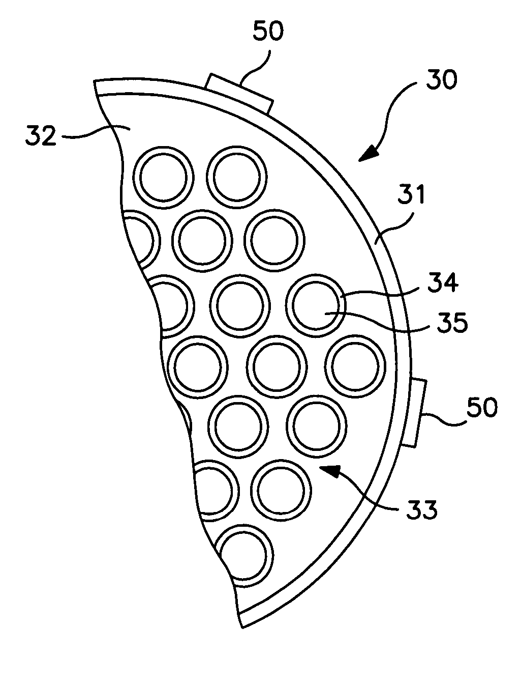
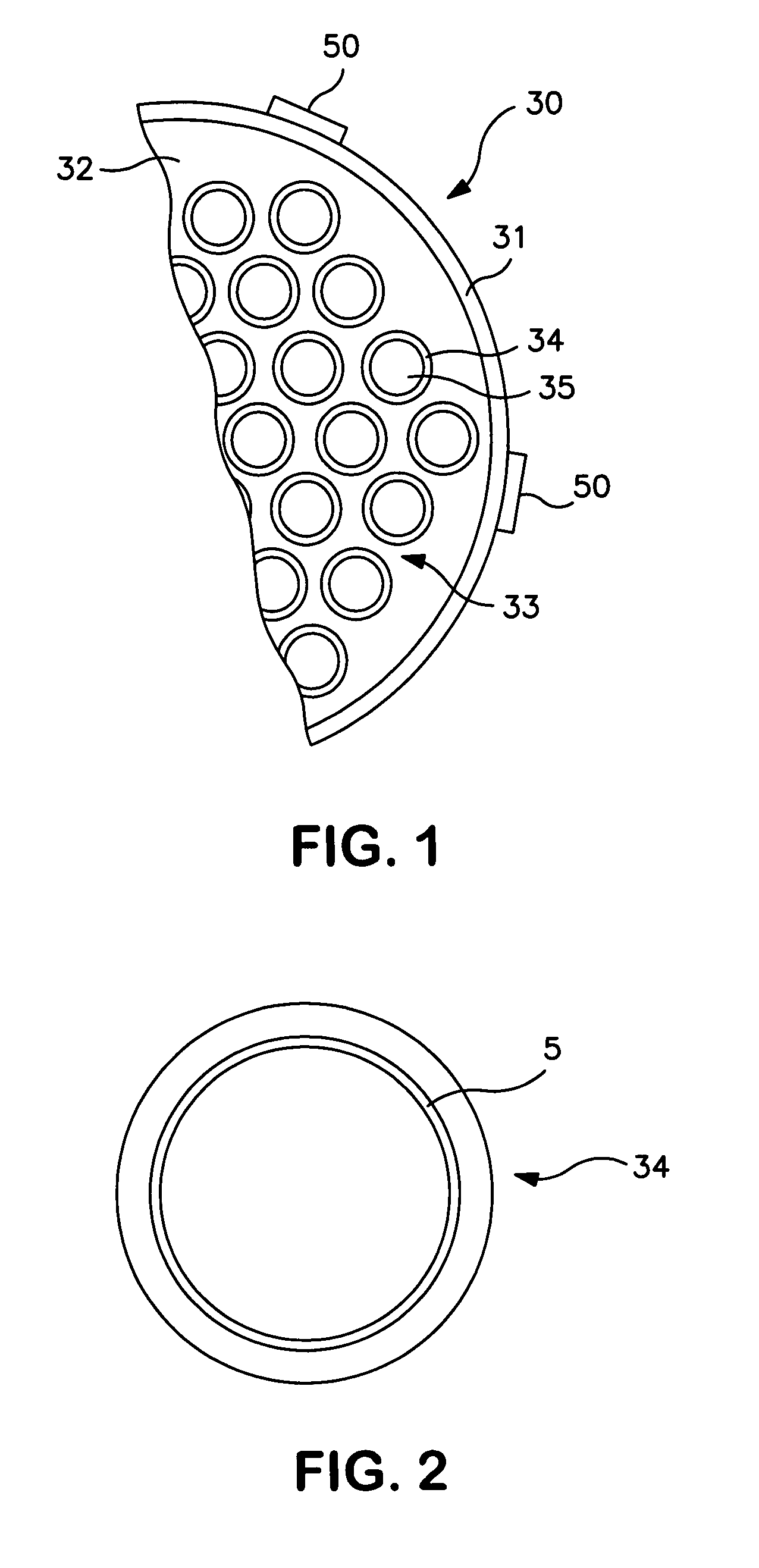
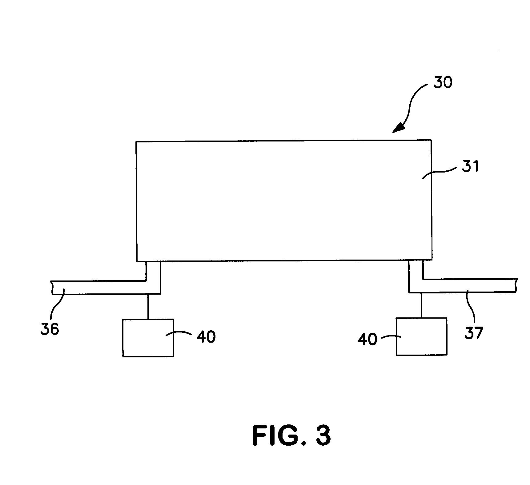
[0024] The present invention winnow be described in greater detail in connection with the attached figures. FIG. 1 is a tube-in-shell heat exchanger 30, which is located upstream from a furnace (not shown) and employs the principles of the present invention. The tube-in-shell heat exchanger 30 disclosed herein illustrates one application of the present invention to reduce sulfidation or sulfidic corrosion and depositional fouling in refinery and petrochemical applications. The tube-in-shell exchanger 30 is just one heat transfer component falling under the scope of the corrosion reduction and fouling mitigation measures in accordance with the present invention. The principles of the present invention are intended to be used in other heat exchangers including but not limited to spiral heat exchangers, tube-in-tube heat exchangers and plate-and-frame heat exchangers having at least one heat transfer element. The principles of the present invention are intended to be employed in other ...


PUM

PropertyMeasurementUnit
Temperatureaaaaaaaaaa
Fractionaaaaaaaaaa
Water contact angleaaaaaaaaaa

Abstract

A method for reducing the formation of deposits on the inner walls of a tubular heat exchanger through which a petroleum-based liquid is flowing comprises applying one of fluid pressure pulsations to the liquid flowing through the tubes of the exchanger and vibration to the heat exchanger to effect a reduction of the viscous boundary layer adjacent the inner walls of the tubular heat exchange surfaces. Reduction of the viscous boundary layer at the tube walls not only reduces the incidence of fouling with its consequential beneficial effect on equipment life but it also has the desirable effect of promoting heat transfer from the tube wall to the liquid in the tubes. Fouling and corrosion are further reduced by the use of a coating on the inner wall surfaces of the exchanger tubes.

Description

CROSS REFERENCE TO RELATED APPLICATIONS [0001] This application relates and claims priority from U.S. Provisional Patent Application No. 60 / 815,845, filed on Jun. 23, 2006, entitled “Reduction of Fouling in Heat Exchangers.”[0002] This application also relates to co-pending U.S. patent application Ser. No. 11 / 304,874, which describes a method of applying low surface energy coatings to heat exchanger surfaces to reduce corrosion and the incidence of fouling on the surfaces, co-pending U.S. Patent Application Ser. No. 60 / 751,985, which describes a corrosion resistant material for reduced fouling in heat exchangers and methods for making coatings of such materials, and co-pending U.S. patent application Ser. No. 11 / 436,802, which describes a method of reducing fouling in heat exchangers by applying a mechanical force to the heat exchanger to induce vibration in the heat exchanger, which causes a shear motion in the liquid flowing within the heat exchanger.FIELD OF THE INVENTION [0003] ...

Claims


Application Information

Patent Timeline
IPC IPC(8): F28D11/06F28F19/02
CPCC10G75/00F28D2021/0059F28F19/02F28F2245/04F28G7/00B01J2219/0245B01J19/1825B01J19/185B01J2219/00094B01J2219/00247B01J2219/0231B01J19/02
Inventor CLAVENNA, LEROY R.CODY, IAN A.COOPER, ASHLEY E.COLGROVE, STEVEHUFFMAN, HUGH L.LOBO, JULIO D.SONG, LIMINWOLF, H. ALANBRONS, GLEN B.LUTZ, GEORGE A.YEGANEH, MOHSEN S.
Owner EXXON RES & ENG CO
Why Eureka
Try Eureka