
Use of friction stir and laser shock processing in oil & gas and petrochemical applications

a technology of friction stir and laser shock processing, which is applied in the direction of furnaces, heat treatment equipment, manufacturing tools, etc., can solve the problems of reducing the mechanical integrity of the joints, affecting the performance of the fusion welding, so as to improve the stress corrosion cracking resistance and environmental cracking resistance, improve the fatigue life, and improve the effect of fatigue li

Inactive Publication Date: 2008-02-07
EXXON RES & ENG CO
View PDF24 Cites 23 Cited by
  • Summary
  • Abstract
  • Description
  • Claims
  • Application Information

AI Technical Summary

Benefits of technology

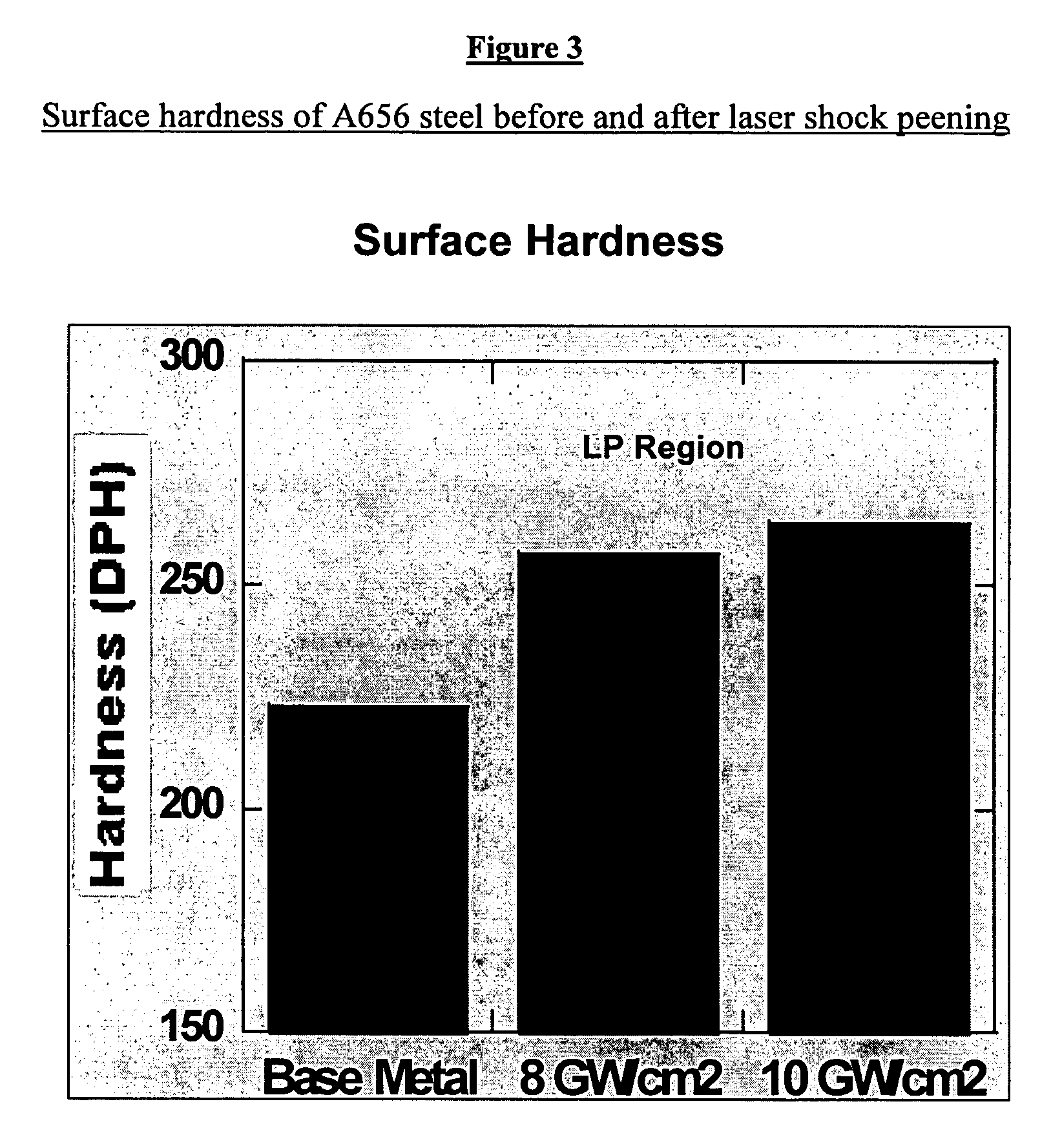
The present patent describes a method of treating ferrous or non-ferrous alloy components by applying an opaque overlay and a transparent overlay to the component, then laser shock processing it to create a coated and treated component with compressive residual stress. The treated component can be used in oil / gas and petrochemical applications. The use of friction stir weldments and laser shock peening in combination provides advantages such as improved fatigue life, stress corrosion cracking resistance, and environmental cracking resistance. The method can also arrest pre-existing cracks, improve surface strength and hardening properties, and decrease the structural thickness of treated regions.

Problems solved by technology

A specially formulated material used for completion components likely to present corrosion problems.
Fatigue: Failure under cyclic loading.
A floating storage device, usually for oil, commonly used where it is not possible or efficient to lay a pipe-line to the shore.
Also, in welding pipes for offshore pipelines, there is the problem of bending stresses that results from the completed pipe hanging off the stern of the lay barge.
In addition, conventional fusion welded joints suffer from other attributes which degrade the mechanical integrity of the joints.
Because of the difficulties associated with such a welding technique, often high carbon steel work pieces are mechanically joined using various types of couplings.
As should be appreciated from the foregoing, conventional fusion welding is prone to crack initiation that originates typically in the HAZ.
In the case of the petrochemical industry where thousands of miles of pipes are installed each year to transport gas, oil and fluids, the costs for repairs are significant.
Hard and low toughness regions in weldment, especially the HAZ, are also prone to develop cracks in service particularly when the welded component is used in an aggressive process environment.
In addition, fusion welding of high strength pipeline steels and other ferrous components used in the oil & gas and petrochemical industry invariably introduces residual tensile stresses and softening in a narrow zone in the heat-affected-zone.
These factors degrade both the toughness and the fatigue resistance of the welded joints because residual tensile stresses increase the propensity for surface-initiated cracks.
Due to residual tensile stresses, the welded joints in steels and corrosion resistant alloys are also susceptible to environmental cracking in corrosive environments.
In off shore oil drilling platforms, conventional welding of steel catenary risers (SCRs) and top tension risers (TTRs) result in high tensile residual stresses.
In one particular example, liquefied natural gas (LNG) and pressurized liquefied natural gas (PLNG) containers also include high integrity weldments that have residual tensile stresses that negatively affect the fatigue resistance and toughness in the weld areas.

Method used


Image

  • Use of friction stir and laser shock processing in oil & gas and petrochemical applications
  • Use of friction stir and laser shock processing in oil & gas and petrochemical applications
  • Use of friction stir and laser shock processing in oil & gas and petrochemical applications

Examples


example 1

LSP Treatment of Steel

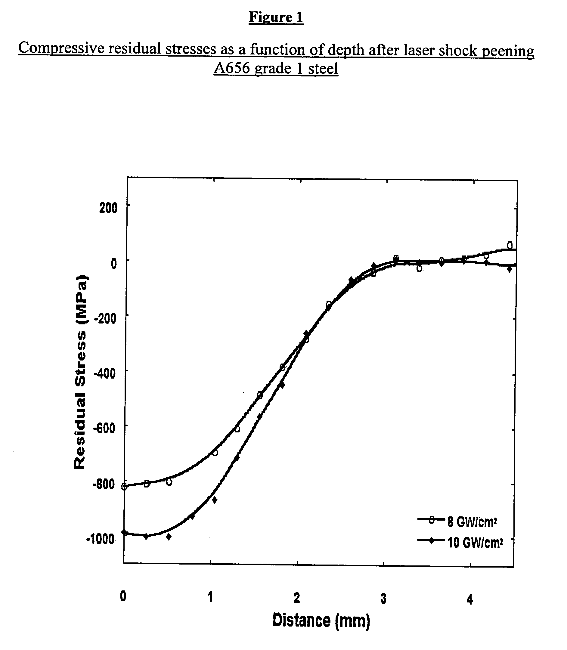
[0097]ASTM A656 grade 1 steel was treated with LSP to determine the residual compressive stresses generated below the surface. FIG. 1 is a plot of the compressive residual stresses induced by LSP treatment as a function of depth from the surface for A656 grade 1 steel for laser power densities of 8 and 10 GW / cm2. Residual stresses were measured using the 3D-Energy Dispersive X-ray Diffraction (3D-EDXRD) method. The residual compressive stresses increase as a function of the laser power density utilized.

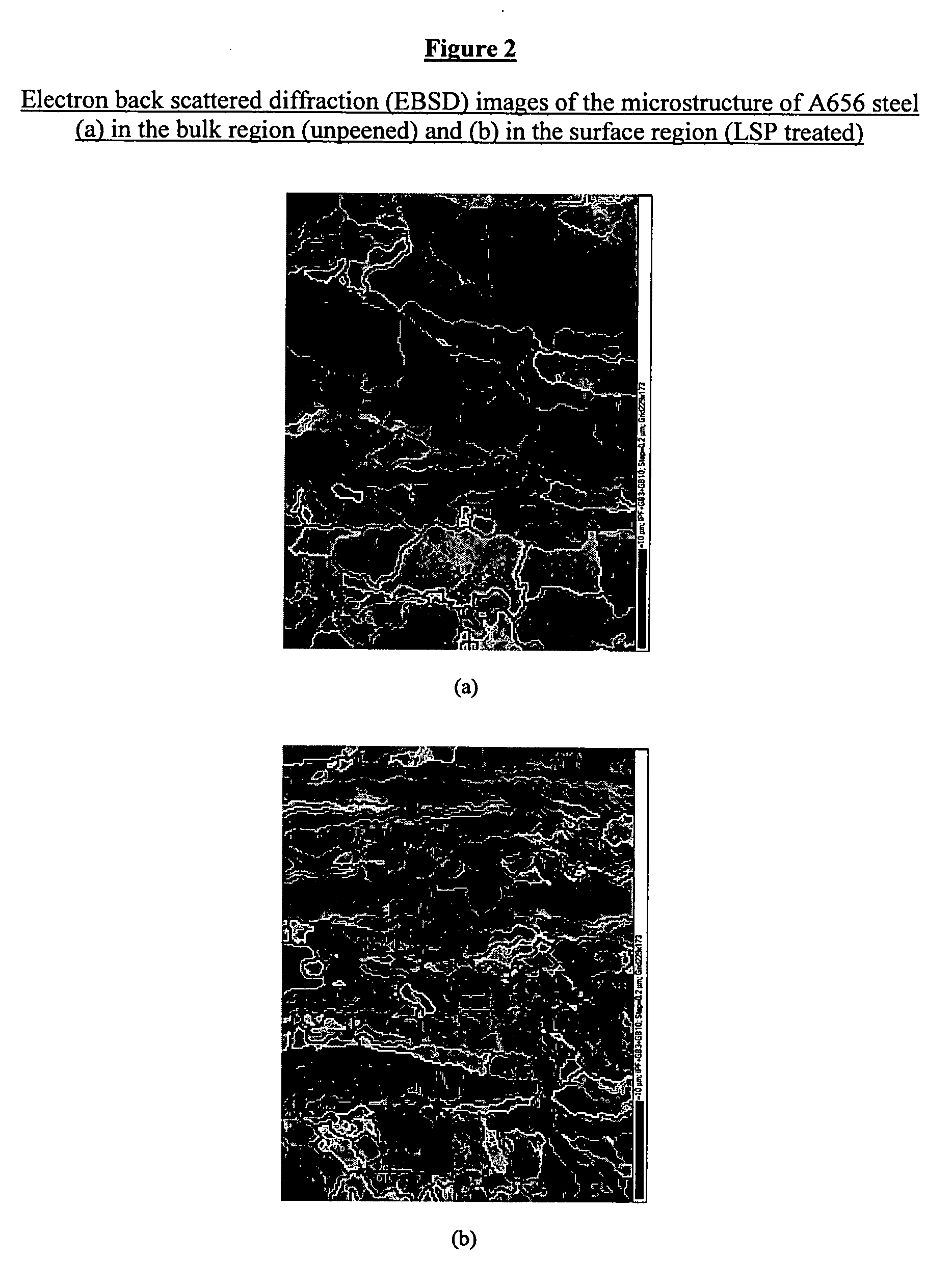
[0098]The A656 grain structure was subsequently measured using electron back scattered diffraction (EBSD). FIG. 2 shows the electron back scattered diffraction (EBSD) images of the microstructure of bulk A656 steel (a) in the bulk region (nonpeened) and (b) the surface region (after laser shock peening). From an examination of the microstructure of bulk A656 in figure (a), the average grain thickness was 3.4 micrometers. In contrast, the microstructure of the las...


PUM

PropertyMeasurementUnit
depthsaaaaaaaaaa
depthsaaaaaaaaaa
wavelengthaaaaaaaaaa

Abstract

The use of friction stir and laser shock processing in oil & gas and / or petrochemical applications is provided by the present invention. The use includes subjecting friction stir weldments, fusion weldments, and other critical regions of ferrous and non-ferrous alloy components used in oil & gas and petrochemical applications to laser shock processing to create residual compressive stresses near the surface of the treated area. The residual compressive forces in the ferrous or non-ferrous components improve properties including, inter alia, surface strength, fatigue life, surface hardness, stress corrosion resistance, fatigue resistance, and environmental cracking resistance. Friction stir and laser shock processing find particular application in high strength pipelines, steel catenary risers, top tension risers, threaded components, liquefied natural gas containers, pressurized liquefied natural gas containers, deep water oil drill strings, riser / casing joints, and well-head equipment.

Description

CROSS-REFERENCE TO RELATED APPLICATION[0001]This application is a Continuation-in-Part of U.S. patent application Ser. No. 11 / 499,800 filed Aug. 4, 2006.FIELD OF THE INVENTION[0002]The present invention relates generally to the field of friction stir and laser shock processing. More specifically, the present invention relates to the application of friction stir and laser shock processing to improve fatigue life of parts and structures used in the oil and gas and petrochemical industries. Still more specifically, the present invention relates to the application of combined friction stir and laser shock processing of welds, weld repairs and treatment of metal parts, particularly but not exclusively, ferrous and non-ferrous metal parts, to provide distinguished properties such as surface strength, high fatigue resistance, high toughness, surface hardness, stress corrosion resistance, environmental cracking resistance and the like.BACKGROUND OF THE INVENTION[0003]For convenience, variou...

Claims


Application Information

Patent Timeline
Patent Type & Authority Applications(United States)
IPC IPC(8): B32B15/00
CPCB23K26/0069B23K26/18Y10T428/12493C21D10/005B23K26/009C21D9/08B23K26/356
Inventor VAUGHN, GLEN A.BANGARU, NARASIMHA-RAO VENKATAKOO, JAYOUNGAYER, RAGHAVANBEESON, DANNY L.THIRUMALAI, NEERAJ S.BAKER, DAVID A.NORMAN, DAVID A.FORD, STEVEN J.FAIRCHILD, DOUGLAS P.
Owner EXXON RES & ENG CO
Learn More