
Triboelectric, Ranging, or Dual Use Security Sensor Cable and Method of Manufacturing Same

a technology of security sensor and triboelectric technology, applied in the direction of cable/conductor manufacturing, conductor, instruments, etc., can solve the problems of not providing any location data, using relatively complex and costly processing means, and cables can be more costly, etc., to achieve simple prior art manufacturing process, easy construction, and easy to manufacture

Inactive Publication Date: 2008-01-31
SENSTAR CORP
View PDF30 Cites 35 Cited by
  • Summary
  • Abstract
  • Description
  • Claims
  • Application Information

AI Technical Summary

Benefits of technology

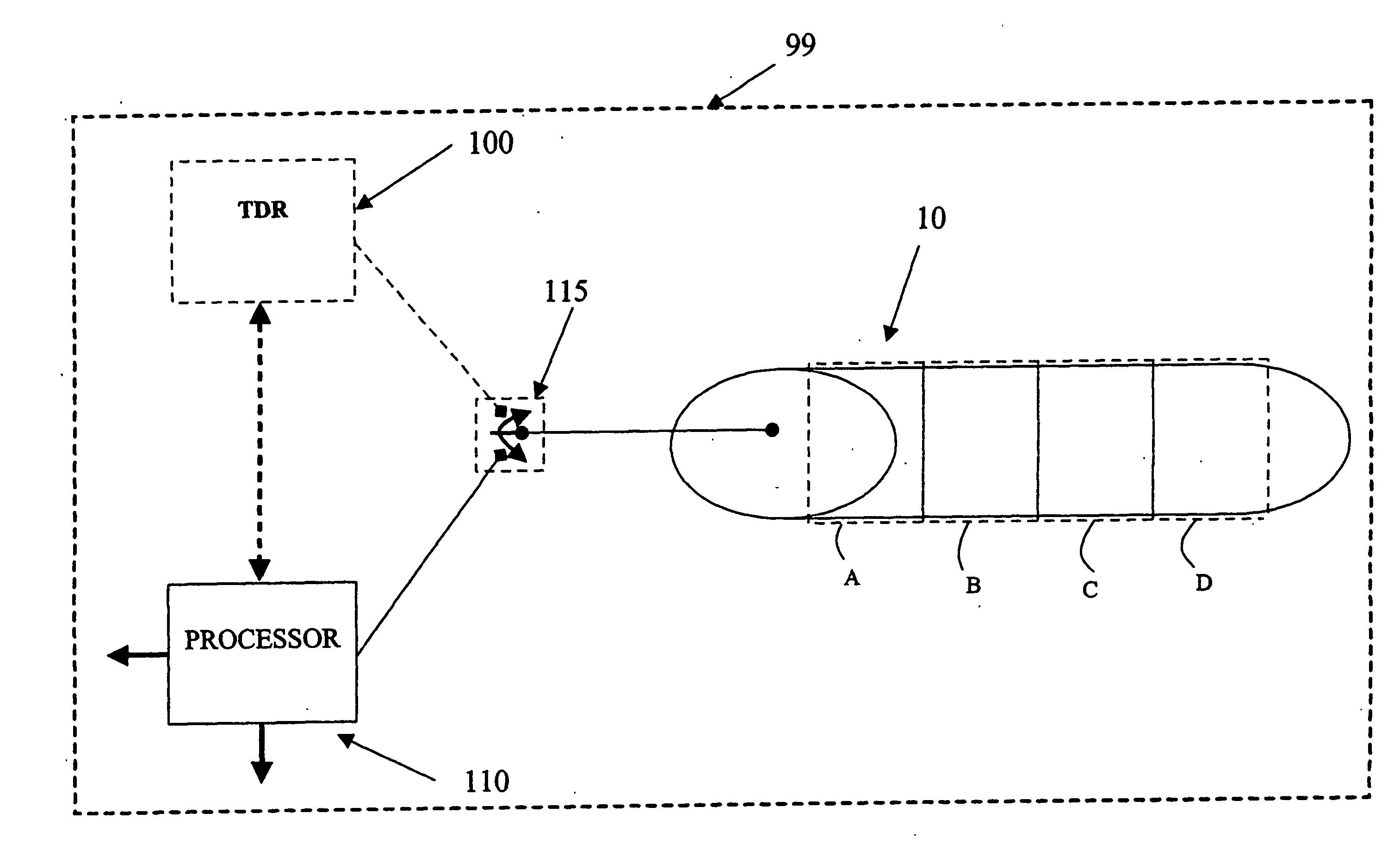
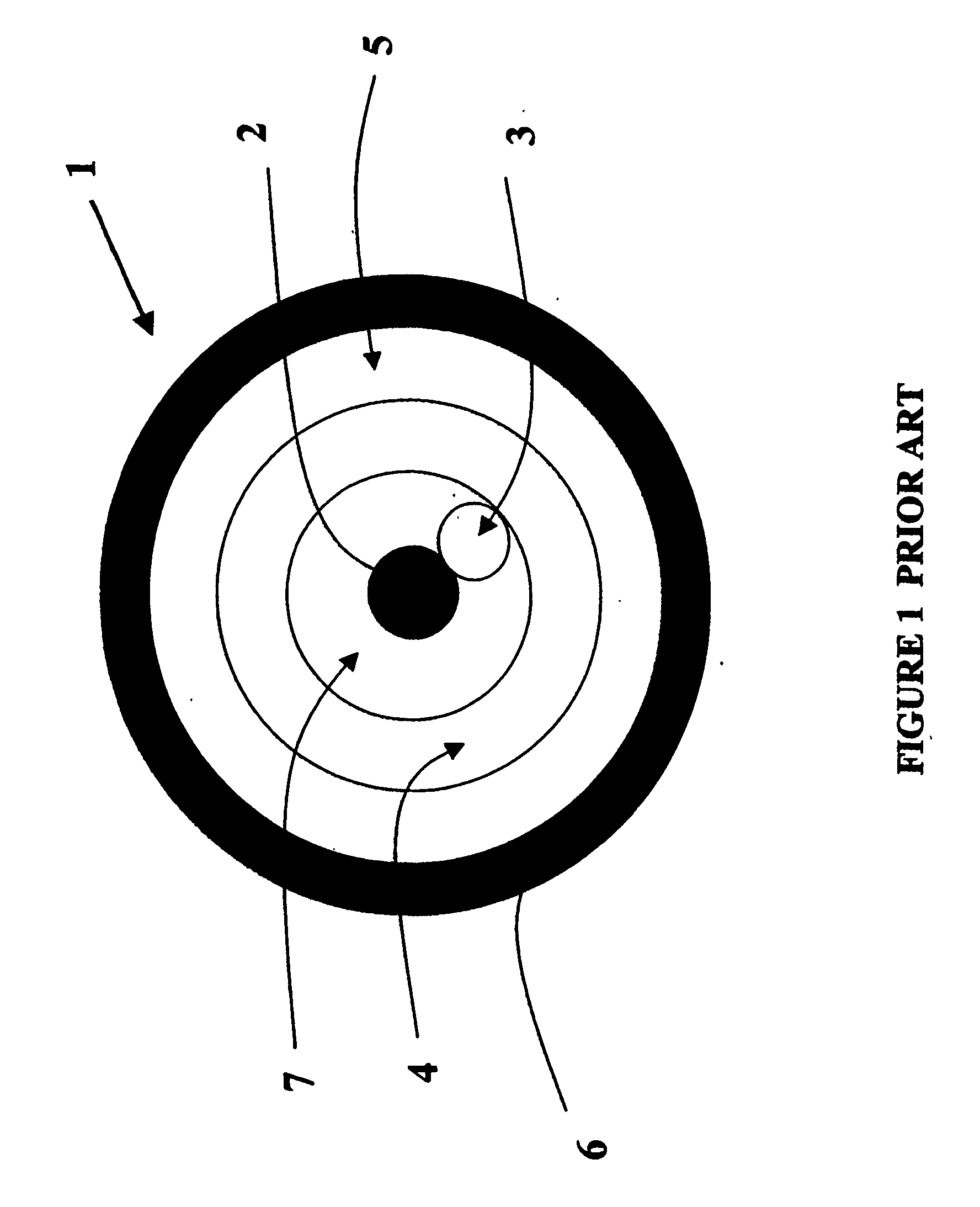
[0036]One advantage of the present invention is it is based on conventional cables, such as RG-62U cable well-known for computer and communication application. The standard RG-62U cable is typically constructed to provide a central conductor of copper-clad steel around which is wound a polyester thread dielectric at a prescribed pitch angle. Around this thread is extruded a further solid polyethylene dielectric tube. An outer conductor or shield of braided copper strands surround the dielectric tube. Finally, a protective outer jacket made of polyvinyl chloride (PVC) or polyethylene is extruded to surround the outer conductor. The combination of the polyester thread and the dielectric tube provide a central conductor that is fixed in place relative to the outer conductor.
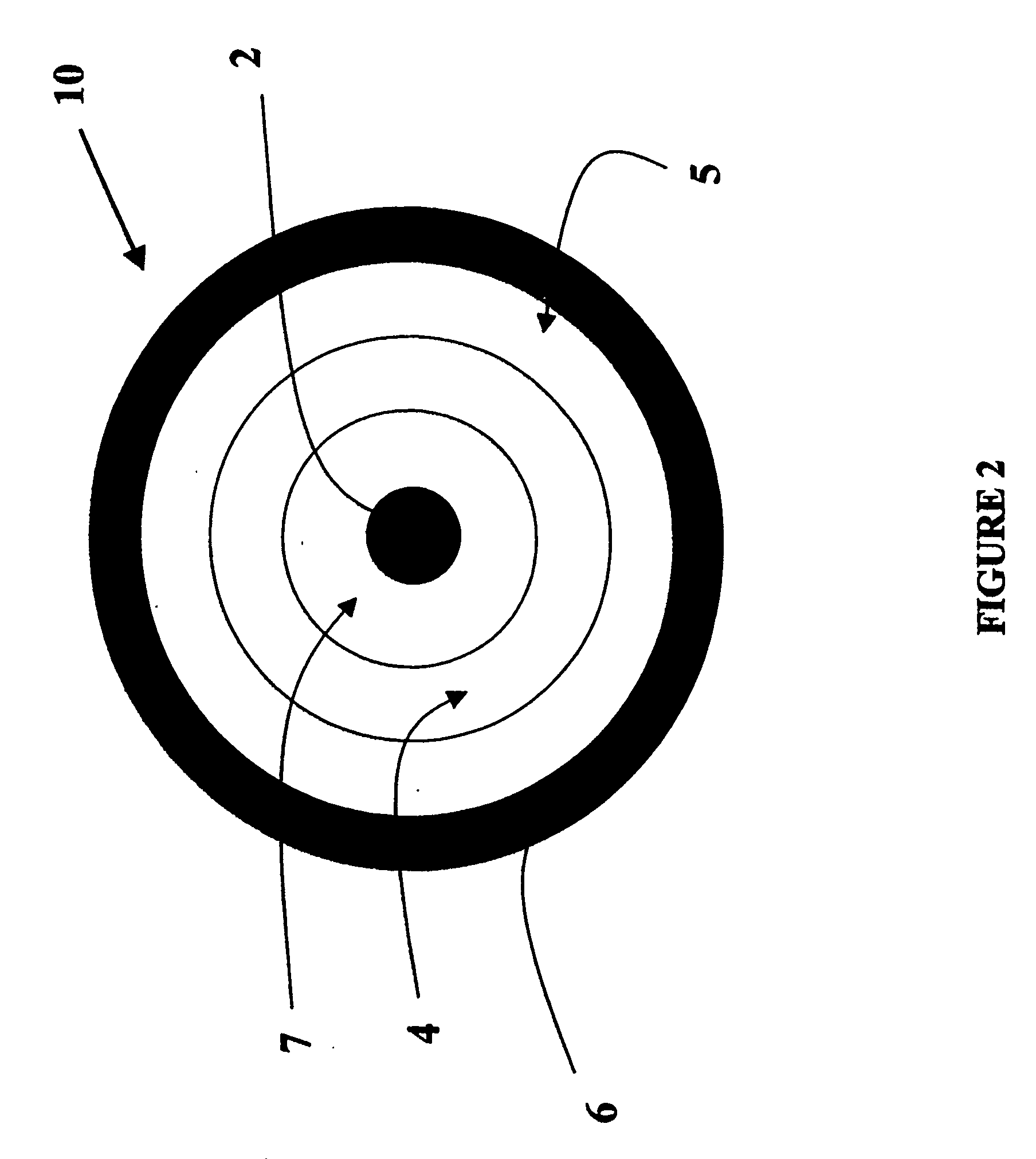
[0037]In the preferred embodiment of the present invention, such conventional RG-62U cable is modified in its construction by omitting the polyester thread, making it threadless. In terms of manufacturing, this sensor cable can be easily constructed using the same or similar processes of extrusion, braiding and jacketing, as well as the same common communication cable components. By eliminating the inner thread in the sensor cable, the center conductor is free to move in the air gap within the dielectric tube, preferably of polyethylene material. Accordingly, the present invention provides an inexpensive method of manufacturing a sensor cable, as the cable parts are readily available and the prior art manufacturing processes are simple and readily available.
[0038]Such a sensor cable is advantageous in that the passive triboelectric properties of the cable, in response to a disturbance, provide a larger voltage response over known cables such as the Intelli-FLEX™ cable which use a more expensive material with a higher dielectric constant. The voltage response to a known disturbance is referred to hereinafter as representing the “sensitivity” of the cable.
[0039]It is also understood that the dielectric material chosen is not limited to polyethylene as materials such as PVC, or foamed polyethylene may be used. In addition, both the passive and the active applications of the cable advantageously provide an inexpensive “dual use” cable for intrusion detection systems.
[0040]Similarly it is understood that manufacturing controls or processing of the material may be employed to enhance the sensitivity or improve signal to noise, such as by creating or maintaining an electret charge.
[0041]In a first aspect, the present invention provides a sensor cable for use in an intrusion detection system having a processor, the sensor cable having an input and an output, both the input and the output of the sensor cable for coupling to the processor, the sensor cable comprising:

Problems solved by technology

One group uses relatively complex and costly processing means to provide location information along long cables, and the other, more frequent simpler processors without location means.
To be equally cost competitive, in the former case the cables can be more costly than the latter case as the processors are less frequent, while in the latter case both the cables and the processors must be inexpensive.
However, there are also fiber optic systems such as IntelliFIBER™ or FiberSensys™, sold by Senstar-Stellar, that are active in that they transmit an optical signal, yet do not provide any location data as they receive a signal modified by a vibration from an intruder, at the opposite cable end.
Many of these sensing cables are costly, either because of the materials used or the complexity of processes for construction.
These fluoropolymer materials are both costly themselves on a per pound basis, and also more difficult to process compared to many other plastics, as they require high melt temperatures to process, or alternatively may have corrosive properties requiring specialized and costly extrusion equipment.
Depending on the magnitude of the response relative to ambient noise, there may be a need for additional cable shielding and amplification or other means to improve signal to noise which would adversely affect cost.
Other cables use magnetic materials that again are difficult and costly to process.
Even with a relatively complicated manufacturing process they are susceptible to field installation problems due to mishandling.
Fiber optic cables are generally simple in construction; however, they are relatively costly, and have an inherent complexity in processes for installing connectors between cables.
Unfortunately, using FEP materials mean cable costs are rather expensive when used for large distances based on their cost per meter length.
However, these keyway conductors are relatively complicated to process and are susceptible to field installation problems if mishandled.
However, the Meryman et al. patent does not disclose the use of a particular dielectric material for the dielectric tubes to enhance the “sensitivity” of the cable, nor does it discuss an active ranging application of the cable.
The Meryman et al. patent disclosure is limited to a device consisting of a cable and signal amplification means.
However, Burney et al. does not disclose an active use of the sensing cable.
Furthermore, the Burney et al. patent does not disclose a loose center conductor construction.
The Gilcher patent also does not disclose the use of the sensor cable in an active system.
However, this cable construction is rather complex in terms of manufacturing processes and, therefore, not practical cost-wise for applications having larger distances.
Harman also teaches a “floating” center conductor, however, the teaching is limited to the center conductor being free to move.
The slot also adds a level of complexity and therefore cost to the manufacture of the cable.
However, Wilson does not disclose a sensor cable having dual use for both a passive and an active ranging cable system, as the cable construction does not provide a loose center conductor.
Moreover, while several background patents teach various sensing cable constructions, a simple and cost-effective manufacturing process is not contemplated in any of the prior art teachings.
Manufacturing processes using electrical testing such as dc “hi-pot” testing can deliberately or inadvertently create electret sensitized cables so it is difficult to determine what is the inherent signal level of a specific material created by processing.

Method used


Image

  • Triboelectric, Ranging, or Dual Use Security Sensor Cable and Method of Manufacturing Same
  • Triboelectric, Ranging, or Dual Use Security Sensor Cable and Method of Manufacturing Same
  • Triboelectric, Ranging, or Dual Use Security Sensor Cable and Method of Manufacturing Same

Examples


second embodiment

[0093]FIG. 3 is an view of a sensor cable 10A constructed and manufactured according to the present invention. The sensor cable 10A shown has a similar construction to that of FIG. 2 with the exception of a thin dielectric layer 15 coated on the center conductor 2A. As is well understood by the skilled artisan, coated conductors are usually form using a thin dielectric layer with material, such as Teflon™. Other dielectric coatings such as PVC are also possible. With this construction the looseness is between the two plastic dielectric layers 15 and 4.

third embodiment

[0094]Another alternative is a twisted pair cable construction, for example, where separate dielectric coated wires are twisted together and possibly shielded. FIG. 4 is an view of a sensor cable 10B constructed and manufactured according to the present invention. The sensor cable 10B consists of a first conductive member 2B coated with a first dielectric layer 15B and loosely disposed within a dielectric tube 4 to move freely within an inner air gap 7, and a second conductive member 5B coated with a second dielectric layer 15B and twisted with the dielectric tube 4. While the two conductive members 2B and 5B are coated with corresponding dielectric layer 15A and 15B, it is readily understood that the dielectric coating may be omitted from the sensor cable construction. It is further readily understood that other cases such as dielectric 4 could be omitted as long as one of the two or more conductors is dielectric coated or jacketed.

[0095]For example, a standard category 5 (CAT5) tw...


PUM

PropertyMeasurementUnit
distancesaaaaaaaaaa
temperatureaaaaaaaaaa
flexibleaaaaaaaaaa

Abstract

The present invention provides an inexpensive security sensor cable, a method for manufacturing of same and an overall security system for using that sensor cable. The sensor cable consists of a central conductor, an air separator, a polyethylene dielectric tube, an outer conductor and an outer protective jacket. The central conductor is loosely centered in the coaxial cable and thus freely movable relative to the dielectric tube. The sensor cable has application either in a passive sensing system or in an active ranging sensing system to determine the location of an intrusion along the cable. For the passive sensing function, when the center conductor moves, it contacts a suitable dielectric material from the triboelectric series, such as polyethylene, which can be processed to produce a charge transfer by triboelectric effect that is measurable as a terminal voltage. In an active system, the central conductor moves within the dielectric in response to a vibration to provide an impedance change that can be sensed. Conventional radio grade cable may be modified in its construction by removing its dielectric thread to manufacture the sensor cable, thus enabling the center conductor to move freely in the air gap within the dielectric tube. An inexpensive method of manufacturing sensor cable is provided as the cable parts are readily available. Such a sensor cable is advantageous in that the passive triboelectric properties of the cable, in response to a disturbance, can provide a larger voltage response over prior art cables.

Description

FIELD OF THE INVENTION[0001]The present invention relates to a security sensor cable. More particularly, the present invention relates to a triboelectric dual use sensor cable, whereby the selection of a particular dielectric material enhances the cable “sensitivity” and reduces manufacturing cost and processing complexity.BACKGROUND OF THE INVENTION[0002]Perimeter intrusion detection systems using linear detection cables can function based on a variety of physical sensing technologies such as RF leaky cable, guided radar, loose conductor active or passive cables, triboelectric or piezoelectric cables, fiber optic cables, electrostatic fields between conductors, etc. Generally they consist of sensor cables deployed along a line, and a processor to interrogate the cables, either active by sending a signal into the cable and assessing the response, or passive where a signal is received from the cable representing an intrusion. If the response output from the injected signal in active ...

Claims


Application Information

Patent Timeline
Patent Type & Authority Applications(United States)
IPC IPC(8): G08B13/22H01B11/18H01B13/016
CPCG08B13/124Y10T29/49123H01B13/0165H01B11/1843
Inventor MAKI, MELVIN C.HARMAN, ROBERT KEITH
Owner SENSTAR CORP
Learn More