Focused ION Beam Apparatus
a technology ion beam, which is applied in the field of focused ion beam apparatus, can solve the problems of mounting or manufacturing error of the apparatus, the inability to produce a corrective magnetic field with high accuracy that can cancel out the external magnetic field, and the strict requirements concerning the spatial uniformity of the corrective magnetic field
- Summary
- Abstract
- Description
- Claims
- Application Information
AI Technical Summary
Benefits of technology
Problems solved by technology
Method used
Image


Examples
first embodiment
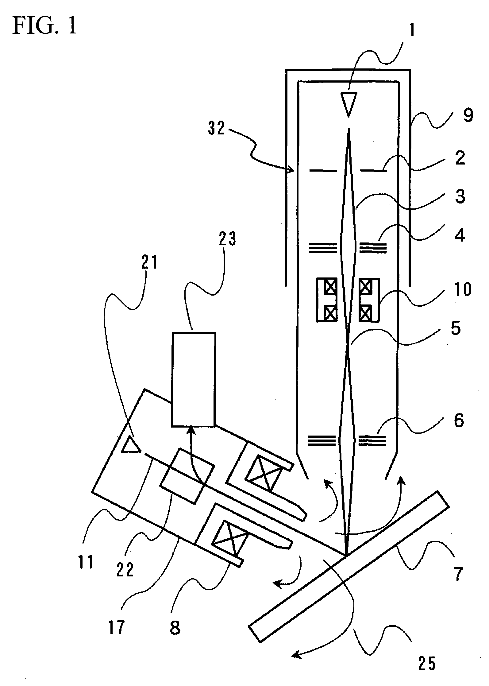
[0041]FIG. 1 schematically shows an overall view of a focused ion beam apparatus (to be hereafter referred to as an FIB apparatus) according to a first embodiment of the invention.
[0042]The focused ion beam apparatus of the present embodiment comprises an ion source 1, an ion beam optical system 32, and an SEM 17, which are disposed in the same sample chamber. The ion beam optical system 32 includes an accelerating electrode 2, an electrostatic condenser lens 4, and an electrostatic objective lens 6.
[0043]A Ga ion emitted by a Ga liquid metal ion source 1 is accelerated by an electric field produced by an accelerating electrode 2, into a Ga ion beam 3 having a kinetic energy of 30 keV The ion beam is then focused by the electrostatic condenser lens 4 once into a crossover 5 (or focused without any crossover and with little change in the beam size), and is further focused on a sample by the electrostatic objective lens 6. The Ga ion beam 3 consists of two isotopes 69Ga and 71Ga, with...
second embodiment
[0091]Normally, excitation of the objective lens of the SEM needs to be frequently varied, as when the focal length is to be changed or when the accelerating voltage is to be changed. In response, the magnitude of the magnetic field that influences the ion beam optical axis also varies, whereby the ion beam spot on the sample 7 is displaced and, in proportion to the amount of such displacement, isotope separation is caused.
[0092]In the present embodiment, in order to solve this problem, a corrective magnetic field control unit 12 is provided, as shown in FIG. 13. In FIG. 13, portions similar to those of the already-described drawings, or portions having functions similar to those of the already-described drawings, are designated with similar numerals and their descriptions are omitted.
[0093]The corrective magnetic field control unit 12 receives a signal proportional to the exciting current to the objective lens 8 (namely, a control signal to the objective lens 8 or a signal based th...
third embodiment
[0095]When there is an external magnetic field that deflects the ion beam other than the magnetic field generated by the objective lens 8 of the SEM 17, where the magnitude of the external magnetic field varies, it is effective to measure the magnetic field that actually exists. In the present embodiment, as shown in FIG. 14, the structure of the second embodiment is additionally provided with a magnetic field probe 14, whose output is fed to the corrective magnetic field control unit 12. The magnetic field probe may comprise a Hall sensor, for example. It may, however, comprise any device as long as it is capable of measuring a magnetic field, such as a magnetoresistor sensor. In FIG. 14, portions designated with numerals not mentioned in the present embodiment are common with FIGS. 1 and 13.
[0096]When there is no magnetic field produced by the objective lens 8 of the SEM 17, the corrective magnetic field control unit 12 causes a current proportional to the magnetic field measured ...
PUM
 Abstract
Description
Claims
Application Information
 - R&D
- Intellectual Property
- Life Sciences
- Materials
- Tech Scout
- Unparalleled Data Quality
- Higher Quality Content
- 60% Fewer Hallucinations
Browse by: Latest US Patents, China's latest patents, Technical Efficacy Thesaurus, Application Domain, Technology Topic, Popular Technical Reports.
© 2025 PatSnap. All rights reserved.Legal|Privacy policy|Modern Slavery Act Transparency Statement|Sitemap|About US| Contact US: help@patsnap.com