
Heat moldable flock transfer with heat resistant, reusable release sheet and methods of making same

a technology of heat-resistant and reusable release sheets, which is applied in the field of molded articles with flocked surfaces, can solve the problems of increasing increasing the cost and time of processing and reprocessing, and increasing the cost of imd technology, so as to reduce the operating cost of molded articles and modest capital investment.

Inactive Publication Date: 2008-01-10
HIGH VOLTAGE GRAPHICS
View PDF99 Cites 39 Cited by
  • Summary
  • Abstract
  • Description
  • Claims
  • Application Information

AI Technical Summary

Benefits of technology

[0009] To protect against burning or heat damage to the flock fibers, the melting, and optionally the softening, point of the heat resistant release sheet is greater than the temperature experienced by the sheet during thermoforming. Preferably, the release sheet has a melting temperatures of at least about 200° C., even more preferably at least about 225° C., and even more preferably at least about 250° C., and the softening point or glass transition temperature of at least about 65° C., even more preferably at least about 75° C., even more preferably at least about 100° C., and even more preferably at least about 150° C. Preferably, the sheet has a thermal conductivity at 23° C. and heat transfer coefficient of no more than about 0.40 W / (m*K), even more preferably no more than about 0.35 W / (m*K), and even more preferably no more than about 0.30 W / (m*K).
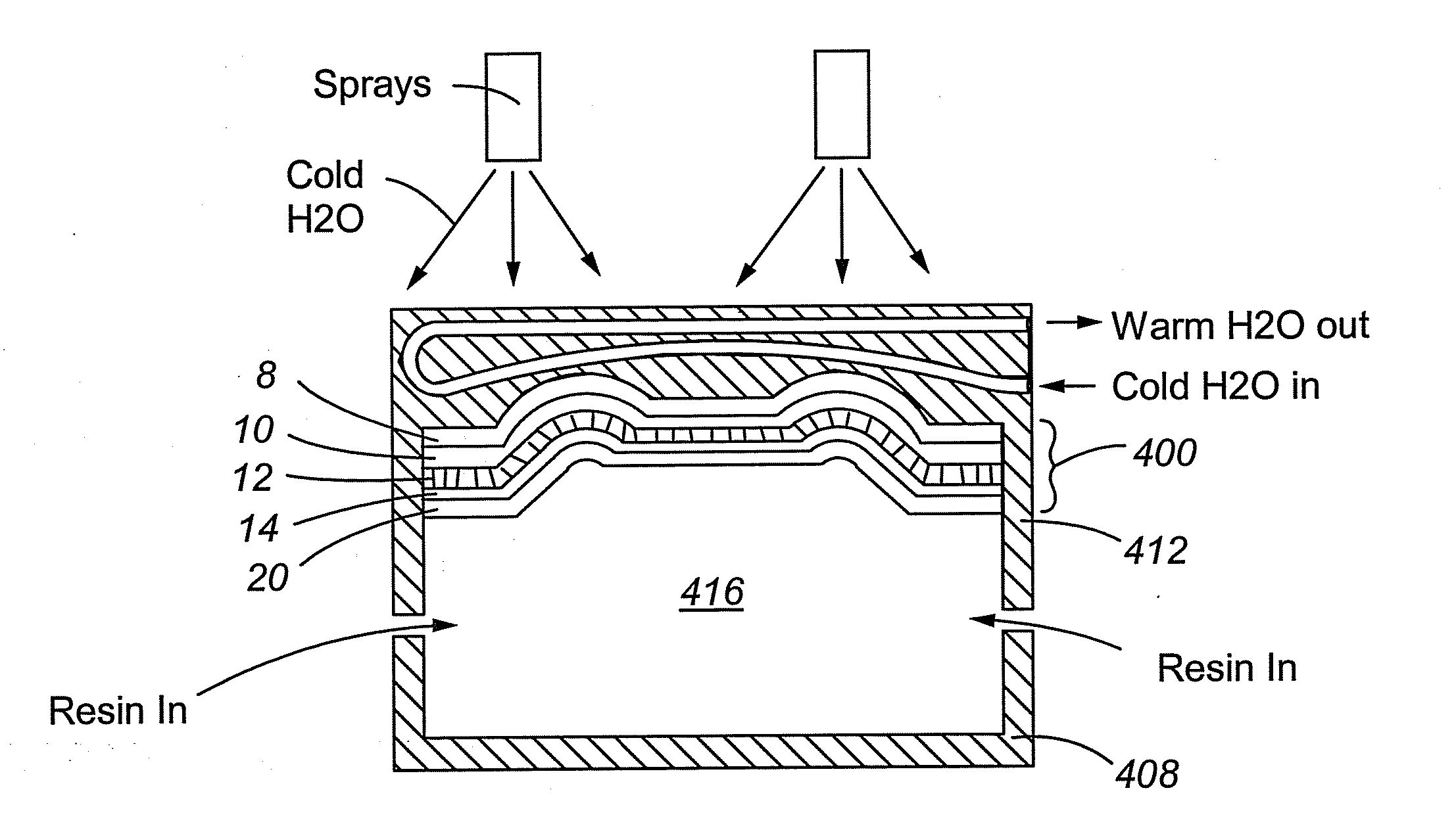
[0013] To protect against burning or heat damage to the flock fibers during thermoforming, the heat resistant release sheet preferably has a melting and / or softening point that is at or above the maximum temperatures experienced by the heat resistant release sheet during thermoforming and / or during molding. Similarly, the backing film preferably has a melting point that is at or above the maximum temperature experienced by the backing film during thermoforming and during molding. The heat resistant release sheet may be removed from the mold insert before molding and subsequently reused in other thermoforming and / or molding operations. To provide for melt bonding with the resin, the backing film has a chemical composition compatible with that of the resin.
[0014] The present invention has an advantage over conventional IMD processes in that the flock fibers can be protected from burning or heat damage experienced by the high temperatures required by the thermoforming and / or molding processes by the use of a heat resistant release sheet. The present invention can also have the advantage of a reusable heat resistant release sheet, which may be used in a plurality of thermoforming and / or molding processes and therefore decrease the operating costs of the production of molded articles. Additionally, the present invention can be relatively simple and requires, at most, a modest capital investment to implement. These and other advantages and aspects of the present invention will be evident from the discussion herein.

Problems solved by technology

These methods are most often post-molding operations requiring additional processing and cost and time.
In addition, the resulting quality of the product is often low, due to the low quality of adhesion or unevenness of the coating.
However, a number of problems have developed with the IMD technology.
By way of example, the ink or decoration is easily damaged by high temperatures experienced during thermoforming of the decoration prior to insertion into the mold and during resin injection into the mold.
The ink or decoration is often discolored or burned because of this heat, leading to an unacceptable and / or unsalable finished article.
Additionally, the polyester carrier sheet typically used during thermoforming and / or molding is a single-use item, thereby increasing operating costs on a per-item basis and reducing the profit realized by the manufacturer of the flocked article.

Method used


Image

  • Heat moldable flock transfer with heat resistant, reusable release sheet and methods of making same
  • Heat moldable flock transfer with heat resistant, reusable release sheet and methods of making same
  • Heat moldable flock transfer with heat resistant, reusable release sheet and methods of making same

Examples


Embodiment Construction

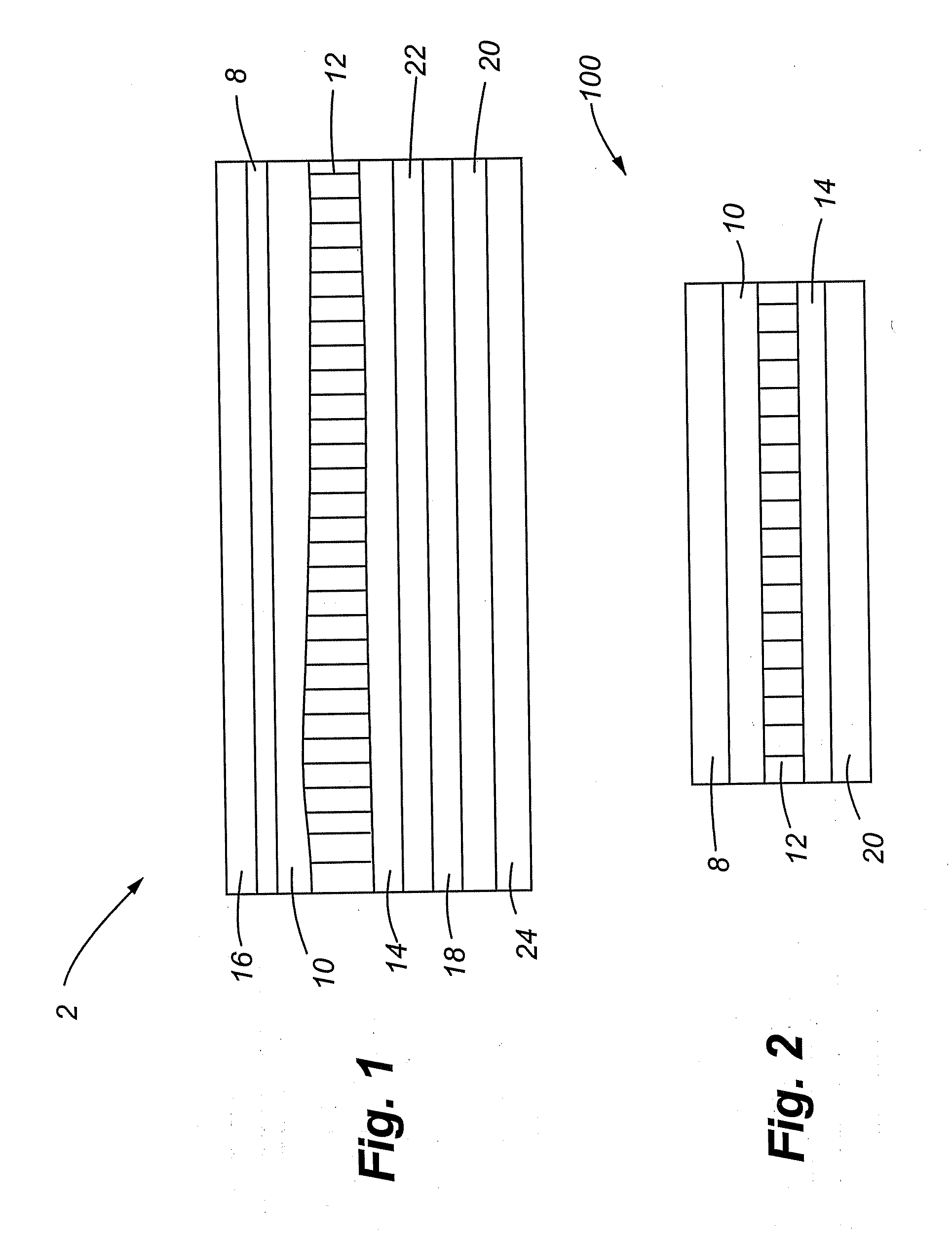
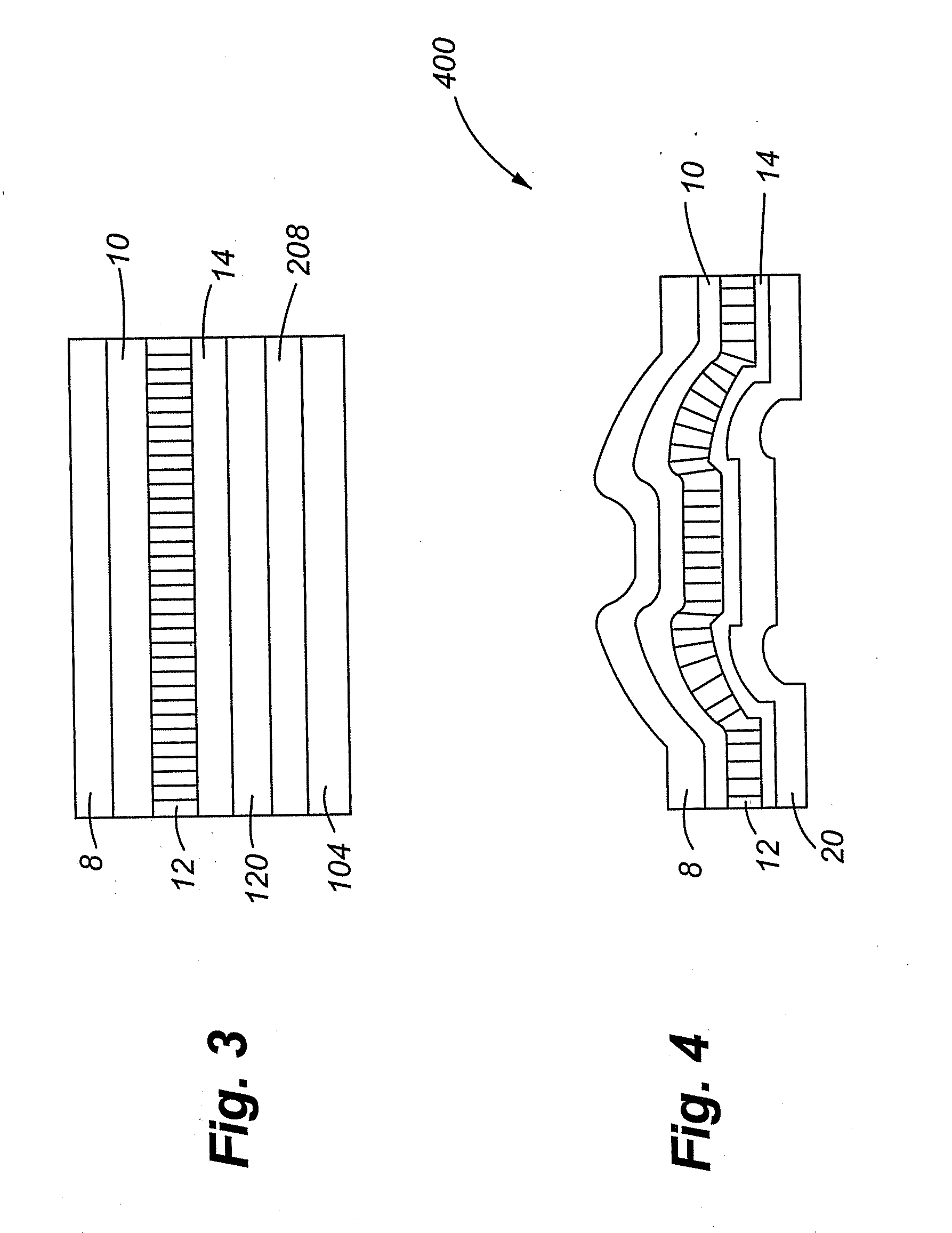
[0024] In one embodiment, a flock heat transfer type media is used rather than ink-printed film inserts or decorations to provide a plush, evenly-coated, three-dimensional single or multi-colored textured decoration that is molded together with the hot resins when the article is formed. Using flock transfer media, a plushly textured decoration is permanently attached to the surface of the molded article. To accomplish this without the risk of burning or heat damaging the flock fibers, a reusable, heat resistant release sheet is utilized such that it contacts first ends of the flock fibers, which first ends are opposing the ends of the flock fibers contacting the permanent adhesive. The heat resistant release sheet preferably completely covers the flock fibers. The heat resistant release sheet may be utilized during a thermoforming step of the flock transfer media, before it is inserted into the mold, to prevent burning or heat damage to the flock fibers from the temperatures experie...


PUM

PropertyMeasurementUnit
melting temperatureaaaaaaaaaa
glass transition temperatureaaaaaaaaaa

Abstract

A method of decorating a molded article is provided in which a mold insert, the mold insert, comprising a plurality of flock fibers, a heat resistant release sheet, a release adhesive, a permanent adhesive layer, and a forming film is thermoformed. During thermoforming, the heat resistant release sheet is positioned between a surface of a forming mold and the flock fibers to protect the flock fibers from overheating.

Description

CROSS-REFERENCE TO RELATED APPLICATIONS [0001] The present application (a) claims the benefits under 35 U.S.C. §119(e) of U.S. Provisional Application 60 / 823,072, filed Aug. 21, 2006, and (b) is a continuation-in-part of U.S. patent application Ser. No. 10 / 394,357, filed Mar. 21, 2003, which is a continuation-in-part of each of U.S. patent application Ser. Nos. 09 / 629,746, filed Jul. 31, 2000; 09 / 621,830, filed Jul. 24, 2000; and 09 / 735,721, filed Dec. 13, 2000, and claims the benefits under 35 U.S.C.§119 of each of U.S. Provisional Application Serial Nos. 60 / 366,580, filed Mar. 21, 2002; 60 / 393,362, filed Jul. 3, 2002; 60 / 416,098, filed Oct. 4, 2002; and 60 / 443,986 filed Jan. 30, 2003, each of which is to Abrams and is incorporated herein by this reference in their entireties.FIELD OF THE INVENTION [0002] This invention relates generally to flocked articles and specifically to molded articles having flocked surfaces. BACKGROUND OF THE INVENTION [0003] It is often desirable to decor...

Claims


Application Information

Patent Timeline
Patent Type & Authority Applications(United States)
IPC IPC(8): B32B33/00
CPCB29C33/68B29C45/1418B29C45/14811B29C45/14827B29C51/008B29C51/145B29C2791/001B29C2791/006B29C2791/007B29K2105/0097B29K2713/00B29K2715/006B29L2009/001B29L2031/722B44C1/10B44C3/04Y10T428/23943
Inventor ABRAMS, LOUIS
Owner HIGH VOLTAGE GRAPHICS
Learn More