
System for Proximity Determination

a proximity determination and system technology, applied in the field of networks, can solve the problems of difficult separation of “network, difference in propagation delay between “external” network and “home”, and likely longer propagation delays in “home” network, so as to achieve the effect of minimizing hardware requirements

Active Publication Date: 2007-12-27
CISCO TECH INC
View PDF9 Cites 68 Cited by
  • Summary
  • Abstract
  • Description
  • Claims
  • Application Information

AI Technical Summary

Benefits of technology

[0017] The present invention, in preferred embodiments thereof, seeks to provide improved methods for securely measuring proximity between network elements in a network while minimizing hardware requirements through using facilities of secure devices and secure elements in the network, for example, which is not meant to be limiting, facilities of Secure Video Processors (SVPs).

Problems solved by technology

In the “external” network propagation delays through switching elements, store-and-forward nodes, and so forth are likely to be much longer than propagation delays in the “home” network.
Such a difference in propagation delay between an “external” network and a “home” is not only due to differences in physical distances within the networks, but also, and mainly, due to additional “hops” between network routers and other network elements.
Propagation delay by itself is not an acceptable measure of proximity between network elements because of the following reasons: It would be very easy for an eavesdropper or a hacker to create a propagation delay measurement deception, It is difficult to separate a “network” propagation delay (due to distance and intermediate agents) from a processing delay which is due to processing time in hardware and / or software of each network element.

Method used


Image

  • System for Proximity Determination
  • System for Proximity Determination
  • System for Proximity Determination

Examples


Embodiment Construction

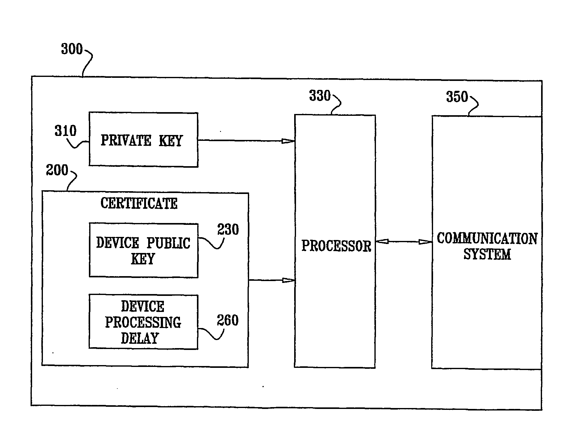
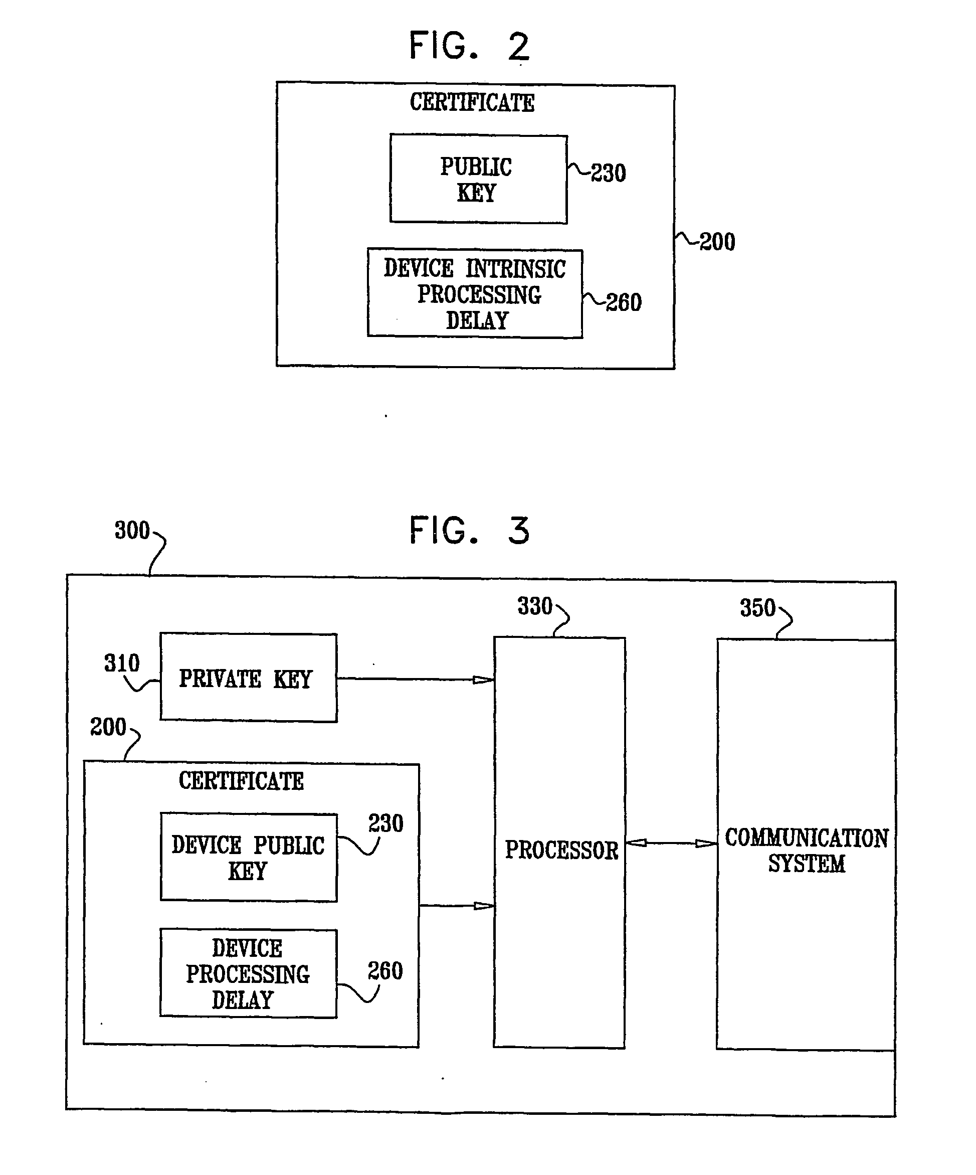
[0067] The concept of Secure Video Processor (SVP) is described in the document found on the World Wide Web at www.svpalliance.org / docs / FAQ.pdf. The SVP is proposed by the SVP Alliance, as described at www.svpalliance.org, for increasing content security in a Home Network environment and a Video On-Demand (VOD) environment. Typically, each SVP device has a Device Certificate, signed by an “Ancestor”. The Certificate contains various pieces of data relating to the device's properties and restrictions placed upon it, and also a public key. The device also has a private key paired to the public key, but such private key is preferably held in secret by the device.

[0068] Content secured by an SVP device, or a system using SVP devices, is scrambled and scrambling keys (or Control Words—CWs) and other control information is passed between individual SVP devices through a Secure Authenticated Channel (SAC).

[0069] As a precursor to SAC setup, any two SVP devices exchange certificates, and ...


PUM


Abstract

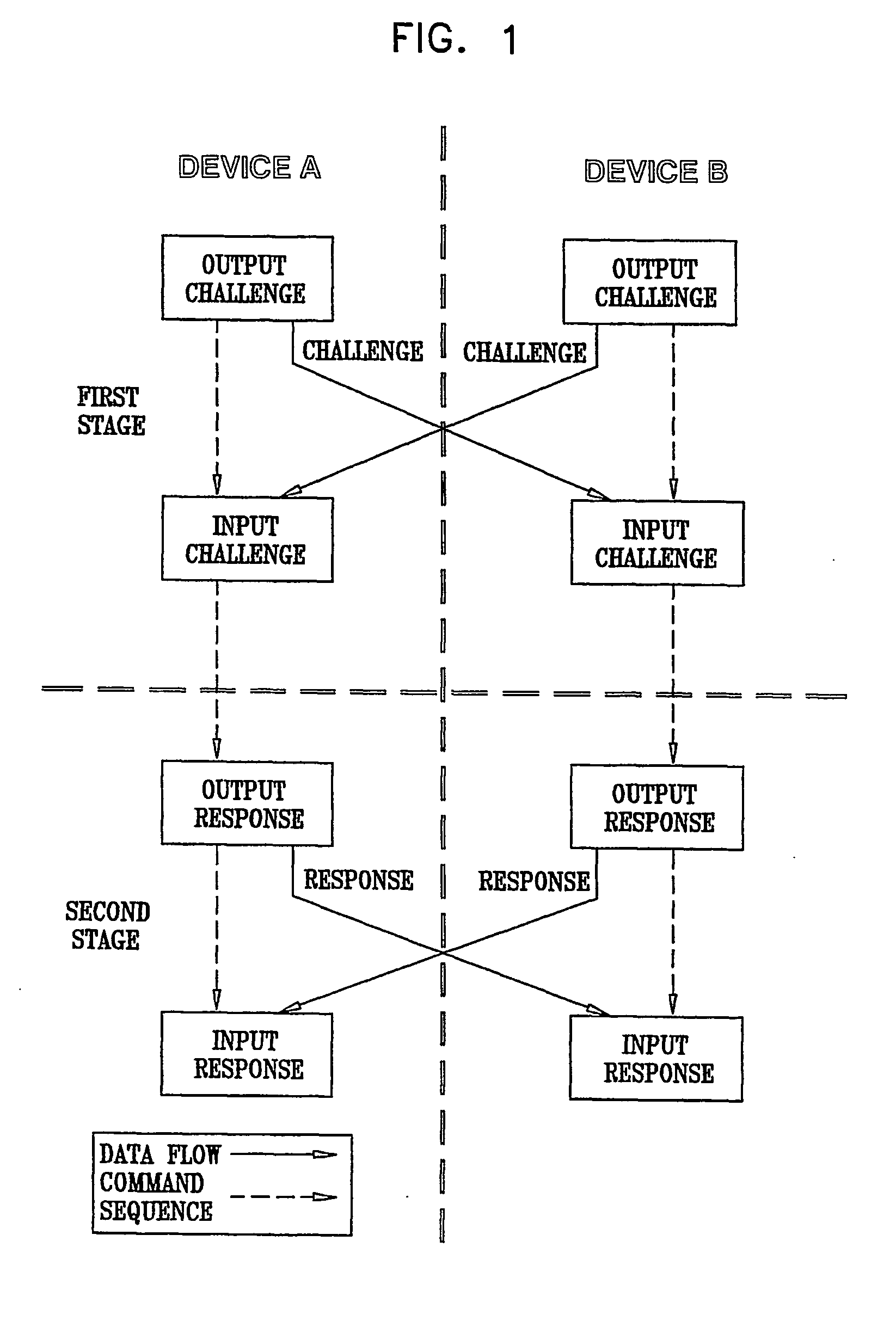
A method for determining proximity between a first device and a second device, the method comprising providing a first device storing a first device private key, the first device having an associated secure first device certificate storing secured information, the secured information comprising a first device public key corresponding to the first device private key, providing a second device storing a second device private key, the second device having an associated secure second device certificate storing secured information, the secured information comprising a second device public key corresponding to the second device private key, and a second device processing delay, providing a copy of the second device certificate to the first device, establishing a secure authenticated channel between the first device and the second device, sending a proximity challenge from the first device to the second device, the proximity challenge including a numeric challenge value, receiving the proximity challenge at the second device, processing the proximity challenge at the second device to produce the response to the proximity challenge, and sending the response to the proximity challenge from the second device to the first device, receiving the response to the proximity challenge at the first device, and performing the following at the first device verifying, at the first device, that the response to the proximity challenge is legitimate, determining a gross time between sending the proximity challenge and receiving the response to the proximity challenge, subtracting the second device processing delay from the gross time to produce a net response time, and comparing the net response time to a first threshold and determining whether the first device and the second device are in proximity based on a result of the comparing. Related methods and apparatus are also described.

Description

CROSS REFERENCE TO RELATED APPLICATION [0001] The present application claims priority from U.S. Provisional Patent Application 60 / 583,338, of Shen-Orr et al, filed 28 Jun. 2004, the disclosure of which is hereby incorporated herein by reference.FIELD OF THE INVENTION [0002] The present invention relates to networks that utilize secure devices and / or secure elements. BACKGROUND OF THE INVENTION [0003] A round-trip signal propagation time in a small “home” network is likely to be considerably smaller than a corresponding time in an “external” network, such as an internet-like network. In the “external” network propagation delays through switching elements, store-and-forward nodes, and so forth are likely to be much longer than propagation delays in the “home” network. A good estimate of an in-home round-trip propagation delay is less than approximately 10 milliseconds, whereas an external network will have a considerably longer round-trip propagation delay. Such a difference in propag...

Claims


Application Information

Patent Timeline
Patent Type & Authority Applications(United States)
IPC IPC(8): H04L9/32H04K1/00
CPCG06F21/33G06F2221/2103G06F2221/2111G06F2221/2129H04L63/0428H04W12/04H04L63/0823H04W12/06H04W24/00H04W12/02H04L63/06H04W12/63
Inventor SHEN-ORR, CHAIM D.HIBSHOOSH, ELIPHAZBELENKY, YAACOV
Owner CISCO TECH INC
Learn More