Materials and methods for producing lenses

a technology of materials and lenses, applied in the field of materials and methods for producing lenses, can solve the problems of misdirecting some of the rays of objects, affecting the lens does not form perfect images, etc., to achieve the effect of facilitating the corrective effect of patients, facilitating the correction of patients, and reducing the optical path differen

Active Publication Date: 2007-12-13
ESSILOR INT CIE GEN DOPTIQUE
View PDF6 Cites 3 Cited by
  • Summary
  • Abstract
  • Description
  • Claims
  • Application Information

AI Technical Summary

Benefits of technology

[0017] Another advantage of using the method provided by the subject invention is that a larger optical path difference (OPD) of a material is achievable. OPD is calculated by multiplying the index of refraction (n) of the material by the material's thickness. The OPD values obtained for wavefront aberrators produced using the method of the subject invention (creating the refractive index profile, allowing for diffusion, then flood irradiating) can be several times higher than the maximum achievable OPD for wavefront aberrators produced using the methods of the prior art (creating the refractive index profile only).
[0018] Being able to produce wavefront aberrators with larger OPD values is very advantageous for human vision correction. Wavefront aberrators of the subject invention with large OPD values facilitate correcting patients with significantly higher wavefront errors than wavefront aberrators of the prior art.

Problems solved by technology

Lenses do not form perfect images; there is always some degree of distortion or aberration introduced by the lens that causes the image to be an imperfect replica of the object.
Thus, aberrations result when the optical system misdirects some of the object's rays.
While this technology is very useful, it gives rise to problems with lens stability.
Because of the varying degrees of cure, a concentration gradient of monomer between different regions exists which may cause the monomer to diffuse over time.
Also, curing of the lesser cured regions after the desired refractive index profile is created can lead to changes in the profile due to reduction of the contrast in the refractive index between the lesser cured and more highly cured regions.
Unfortunately a need for specific storage conditions could limit the number of practical applications for the wavefront aberrator.
Because humans wear their glasses in a variety of conditions (hot / cold, humid / dry, sunny / dark), temperature and light exposure can not be easily controlled.

Method used


Image

  • Materials and methods for producing lenses
  • Materials and methods for producing lenses
  • Materials and methods for producing lenses

Examples


example 1

Wavefront Aberrator Sample Preparation

[0056] Part I: In a 500 mL flask, 100 g of poly[(phenylglycidyl ether)-co-formaldehyde], 49.42 g of diallylether Bisphenol A, 0.2761 g of Irgacure 184, and 0.0552 g of N-PAL were dissolved in acetone. The mixture was then filtered through a 0.2 μm syringe filter into another clean 500 mL flask. The filtrate was rotary evaporated at 60° C. for 2 hours to evaporate all acetone.

[0057] Part II: In another 500 mL flask, 3.27 g of tetrabutyl ammonium bromide, and 150 g of trimethylolpropane tris(3-mercaptopropionate) were dissolved in acetone. The mixture was then filtered through a 0.2 μm syringe filter into another clean 500 mL flask. The filtrate was rotary evaporated at 50° C. for 2 hours to evaporate all acetone.

[0058] A portion of Parts I and II were mixed in a ratio of 1.157:1, respectively. The Part I composition was weighed carefully in a 20 mL scintillation vial. Based on the amount of Part I formulation, the calculated amount of Part II ...

example 2

Correction of Aberrations of Optical Systems

[0060] A plano power optical element was prepared as described in Example 1. The optical element was placed in a hot box with a lens holder at 85 C. An EXFO Omnicure UV lamp with a square cross-section mixing rod was used to produce a uniform beam of ultraviolet radiation (Intensity ≈9.5 mW / cm2) which irradiated a DLP micro-mirror array.

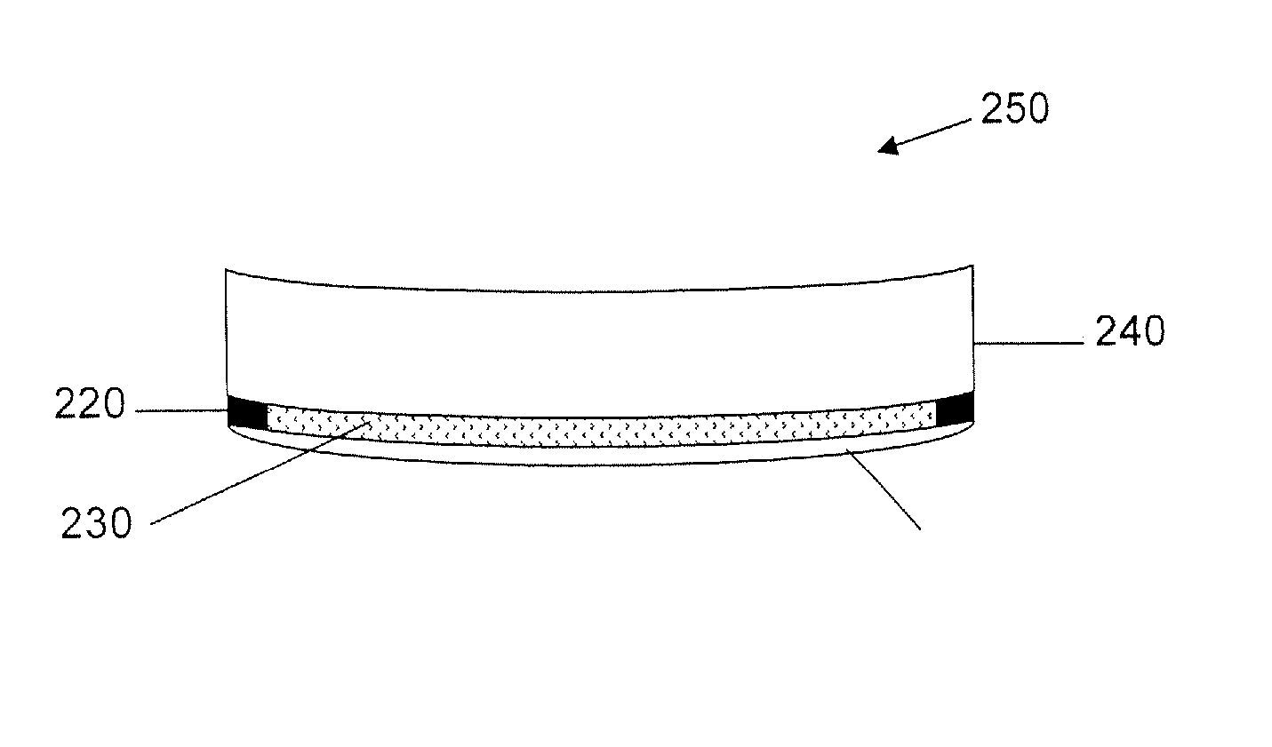
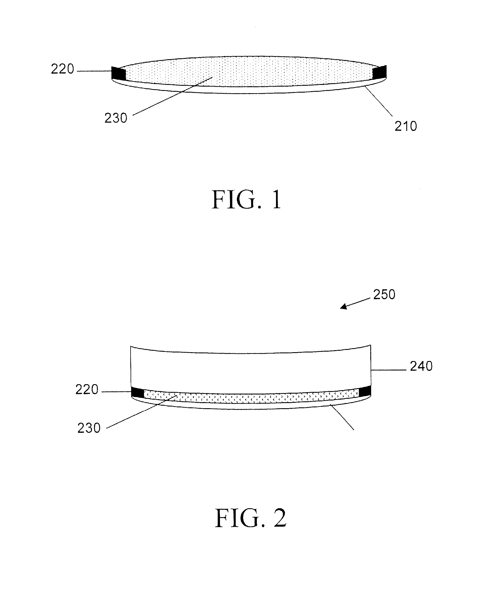
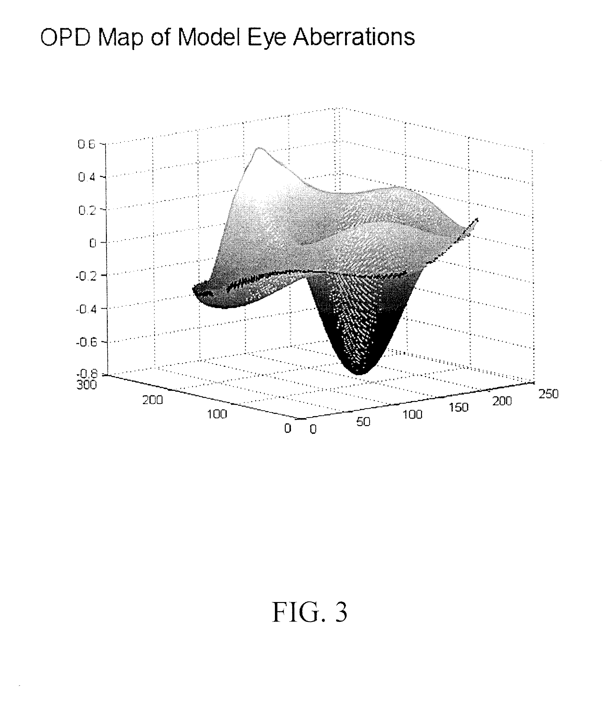
[0061] The central region of the sandwiched gel in the lens assembly was exposed to an ultraviolet radiation pattern re-imaged from the DLP corresponding to the aberrations of a model eye (see FIG. 3) for 100 seconds. A wavefront lensometer was used to measure the OPD pattern created in the sandwiched gel 230 as a result of the ultraviolet exposure. The peak-to-valley of the OPD pattern was measured to be 0.446 microns. The hot box temperature was adjusted to 105 C and the lens was kept in the hot box for an additional 4 hours to force diffusion of uncured monomer into the regions where monomer had been d...

example 3

Diffusion Rate and OPD Growth Rate Control

[0065] Two plano power optical elements were prepared as described in Example 1. Each optical element was placed in a hot box with a lens holder at 85 C. The DLP system of Example 2 was used to expose the formulation layer of each optical element to an ultraviolet radiation pattern corresponding to the aberrations of a model eye. The first optical element was exposed to the pattern for 60 seconds, and the second optical element was exposed for 120 seconds.

[0066] A wavefront lensometer was used to measure the resulting OPD pattern in each optical element. The peak-to-valley the OPD pattern in the first optical element was 0.235 microns, and the peak-to-valley for the second optical element was 0.473 microns.

[0067] The temperature of the lens hot box was adjusted to 105 C. The first optical element was kept in the lens hot box at 105 C for 4 hours and 8 minutes, and the second optical element was kept at 105 C for 3 hours and 32 minutes to ...


PUM

PropertyMeasurementUnit
optical path differenceaaaaaaaaaa
thicknessaaaaaaaaaa
thicknessaaaaaaaaaa

Abstract

The subject invention provides methods for creating wavefront aberrators with a desired refractive index profile that is stable against thermal and/or solar exposure. The invention further provides wavefront aberrators produced according to the methods described herein.

Description

[0001] BACKGROUND OF THE INVENTION [0002] A lens is a device usually formed from a piece of shaped glass or plastic that causes light to either converge and concentrate, or to diverge. One important use of lenses is as a prosthetic for the correction of visual impairments such as myopia, hyperopia and presbyopia. Other uses are in imaging systems such as a monocular, binoculars, telescopes, spotting scopes, telescopic gun sights, theodolites, microscopes, and cameras (photographic lens). [0003] Lenses do not form perfect images; there is always some degree of distortion or aberration introduced by the lens that causes the image to be an imperfect replica of the object. Thus, aberrations result when the optical system misdirects some of the object's rays. There are several types of aberration that can affect image quality. Some aberrations occur when electromagnetic radiation of one wavelength is being imaged (monochromatic aberrations), and others occur when electromagnetic radiatio...

Claims


Application Information

Patent Timeline
Patent Type & Authority Applications(United States)
IPC IPC(8): G02B1/00B29C65/02
CPCB29D11/00355G02B5/208G02B3/0087G02B1/041G02C2202/12G02C2202/16
Inventor DREHER, ANDREAS W.JETHMALANI, JAGDISH M.SVERDRUP, LARRY H.CHOMYN, JEFFREY S.
Owner ESSILOR INT CIE GEN DOPTIQUE
Why Eureka
Try Eureka