Eureka AIR delivers breakthrough ideas for toughest innovation challenges, trusted by R&D personnel around the world.

DAC based switching power amplifier

a power amplifier and switching technology, applied in the field of communication systems, can solve the problems of limited wideband applications of conventional power supply modulation techniques, several challenges for polar transmitters,

Inactive Publication Date: 2007-11-29
AVAGO TECH INT SALES PTE LTD
View PDF4 Cites 42 Cited by
  • Summary
  • Abstract
  • Description
  • Claims
  • Application Information

AI Technical Summary

Benefits of technology

The present invention is about a device and methods for using it. The technical effects of the invention will be explained in detail in the following description with reference to the accompanying drawings.

Problems solved by technology

In addition, polar transmitters also have several challenges related to amplitude modulation and power control.
Therefore, conventional power supply modulation techniques are limited for many wideband applications.

Method used


Image

  • DAC based switching power amplifier
  • DAC based switching power amplifier
  • DAC based switching power amplifier

Examples


Embodiment Construction

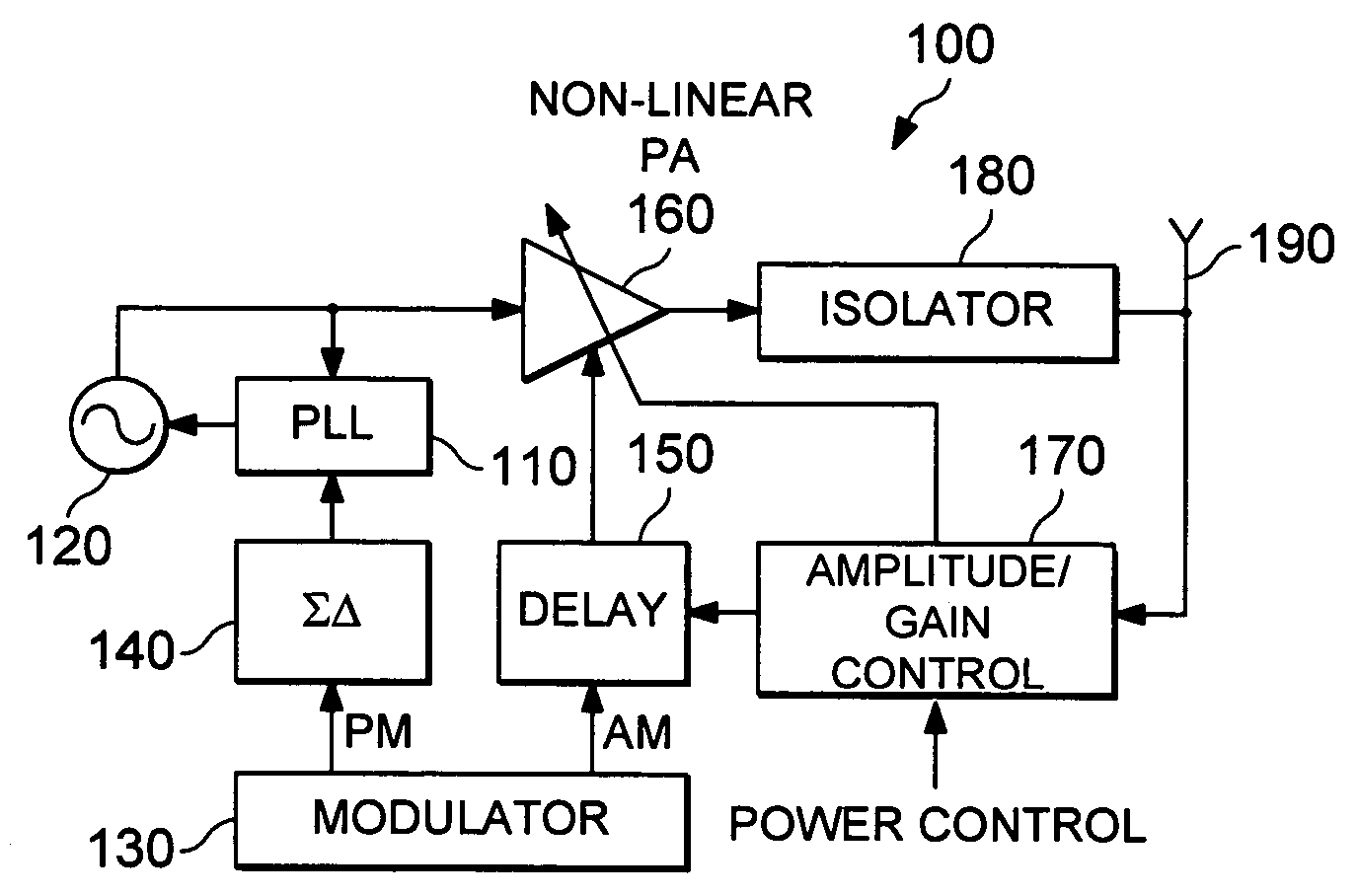
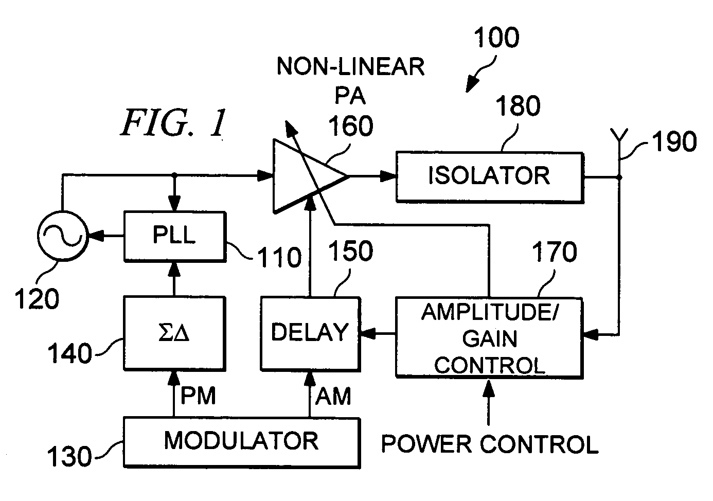
[0030]FIG. 1 is a schematic block diagram illustrating a conventional polar transmitter 100. In FIG. 1, it is assumed that a baseband processor delivers baseband envelope signal r(t) and baseband phase signal θ(t) to the polar transmitter for further processing and RF transmission. The polar transmitter 100 includes a modulator 130 that performs the necessary pulse shaping, modulation, and interpolation filtering to produce a digital phase-modulated signal and a digital amplitude-modulated signal, each at some intermediate frequency (IF) carrier fIF. Additional spectral shaping may be performed on the phase-modulated signal by using a delta-sigma modulator 140. Although not shown, the polar transmitter 100 further includes digital-to-analog converters (DACs) that convert the IF phase-modulated signal and IF amplitude-modulated signal from digital to analog.

[0031]The remaining components of the polar transmitter 100 are a phase-locked loop (PLL) 110, a local oscillator (LO) 120, a de...


PUM


Abstract

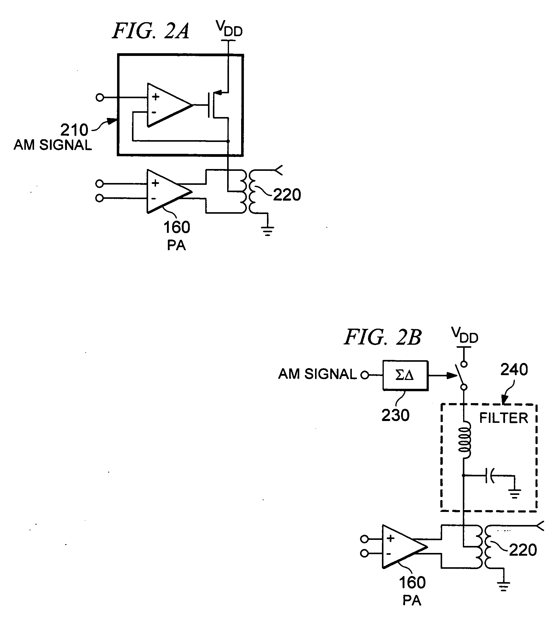
A power amplifier for use in a transmitter includes a first transistor having an input, a first node and a second node, a second transistor having an input, a first node and a second node and a digital to analog conversion module. The input of the first transistor is operably coupled to receive a first input, while the input of the second transistor is operably coupled to receive a second input. The second nodes of the first and second transistors provide an output of the power amplifier. The digital to analog conversion module is operably coupled to control current through the first and second transistors based on at least one of a power control signal and an amplitude modulation control signal.

Description

CROSS REFERENCE TO RELATED PATENTS[0001]This U.S. application for patent claims the benefit of the filing date of U.S. Provisional Patent Application entitled, DAC BASED SWITCHING POWER AMPLIFIER, Attorney Docket No. BP5330, having Ser. No. ______, filed on Apr. 6, 2006, which is incorporated herein by reference for all purposes.STATEMENT REGARDING FEDERALLY SPONSORED RESEARCH OR DEVELOPMENT [0002]NOT APPLICABLEINCORPORATION-BY-REFERENCE OF MATERIAL SUBMITTED ON A COMPACT DISC [0003]NOT APPLICABLEBACKGROUND OF THE INVENTION[0004]1. Technical Field of the Invention[0005]The present invention relates to communication systems and, more particularly, to power amplifiers used within transmitters.[0006]2. Description of Related Art[0007]Modern wireless RF transmitters for applications, such as cellular, personal, and satellite communications, employ digital modulation schemes, such as frequency shift keying (FSK), phase shift keying (PSK), and variants thereof, often in combination with c...

Claims


Application Information

Patent Timeline
Patent Type & Authority Applications(United States)
IPC IPC(8): H04B1/04
CPCH03C5/00H03G3/001H03F1/0272H03F1/0277H03F3/24H03F3/45188H03F3/72H03F2200/324H03F2200/331H03F2200/393H03F2203/45466H03F2203/45616H03F2203/45641H03F2203/45731H03F2203/7215H03F1/0205
Inventor ROFOUGARAN, AHMADREZA (REZA)SHAMELI, AMIN
Owner AVAGO TECH INT SALES PTE LTD
Why Eureka
Eureka Blog
Learn More